XBee S1 Manual Download Page 16

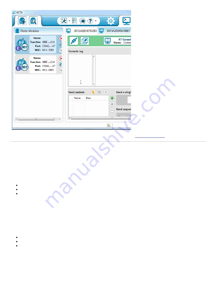
If that worked, then your XBees are configured to talk to each other! If not, check out th

troubleshooting page

.

That your XBees can talk to each other out of the box is no real surprise. They're all configured, by default, to be on the same network
with the same addresses. That might be OK, but what if your neighbor is running an XBee-based robot control network, while you're trying
to automate your house? Every time they try to roll a bot forward, your garage door might open! To be safe, you should configure your
XBees to operate on a unique network. Fortunately, that, and most other XBee settings are easy to change. On to the next page!

Configuring Networks

XBees can be configured with few different modes to transmit/receive signals. These include:

Transparent Mode
API Mode
I/O Line Passing

For simplicity, we will be using a pair of XBee Series 1 (or XBee Series 3 configured with the 802.15.4 protocol) set in transparent mode to
replace a wired serial UART connection.

Transparent Mode

As we've mentioned, XBees are awesome because they're highly -- and easily -- configurable. Most of the XBee configuration settings
come down to controlling which other XBees it can talk to. On this page, we'll show you how to configure three of the most important XBee
settings there are for a point-to-point communication:

PAN ID
MY Address
Destination Address

Channel (CH)

There are a few levels to XBee networks. First, there's the 

channel

. This controls the frequency band that your XBee communicates over.

Most XBee's operate on the 2.4GHz 802.15.4 band, and the channel further calibrates the operating frequency within that band. You can
usually leave the channel setting alone, or at least make sure every XBee you want to have on the same network operates on the same

Page 16 of 24

Summary of Contents for S1

Page 1: ...ble low cost bi directional communication at moderate speeds XBee may be the solution for you XBees are hugely popular wireless transceivers for a number of reasons They reflexible they send and recei...

Page 2: ...ur computer and an XBee They re used to configure your XBee and pass data to and from your computer Depending on which explorer you have you may also need a matchingmini B USB or serial cables At leas...

Page 3: ...toggling the XBee 3 s reset pin To automate this during startup you can solder a wire between the reset pin and the 3 3V I O pin of a microcontroller Toggling the reset pin with a minimum of 50ns 100n...

Page 4: ...ou ever need to debug your XBee RX TX RSSI signal strength indicator and a power indicator This board also breaks out each of the XBee s I O pins to a pair of breadboard compatible headers So if you w...

Page 5: ...r USB Dongle The XBee Explorer Dongle is an extension of the Explorer In fact the only real difference between this and its predecessor is the USB connector The Dongle can be connected directly to you...

Page 6: ...hren but still shares most of the same features There are RX and TX LEDs reset button break out pins and a voltage regulator One additional feature that the Serial Explorer has is an On Off switch on...

Page 7: ...ugh current for the XBee you are using Wall Adapter Power Supply 9VDC 650mA TOL 00298 12 Retired Favorited Favorite 23 Wish List Wall Adapter Power Supply 12VDC 600mA TOL 09442 13 Retired Favorited Fa...

Page 8: ...e next pages How to Install FTDI Drivers June 4 2013 How to install drivers for the FTDI Basic on Windows Mac OS X and Linux Favorited Favorite 8 Basic Assembly Plug In an XBee Time to assemble the XB...

Page 9: ...O line passing can be found in the XBee s user manual Starting With X CTU X CTU is free software provided by Digi the manufacturer of XBee which we use toconfigure and manage XBees and test XBee netw...

Page 10: ...dows users should look for the entry that says USB Serial Port and Mac users should look for something like usbserial XXXXXXXX if you re using a USB XBee board If you re using a Serial Explorer instea...

Page 11: ...shows an XBee Series 1 connected to the XCTU As you can see by scrolling down the right half there area lot of configuration settings available We ll get to some of those later For now though verify t...

Page 12: ...Series 2 firmware For the scope of this tutorial we will be using the Digi XBee3 802 15 4 TH function set You will then select the firmware version In this case it is2002 When ready click the Update b...

Page 13: ...gain To test communication between your XBee s you ll need to connect your second XBee to a computer as well That means doing the Add device dance one more time if you have not already If you have ano...

Page 14: ...ft The configuration values shown are for the highlighted XBee If you re ever unsure which XBee is which try to match up theMAC numbers These numbers are printed on a sticker on the bottom side of you...

Page 15: ...t s connected to If you have two XBees connected to your computer you can switch between each radio s console by selecting the device on the left First open a serial connection on each device by click...

Page 16: ...e Passing For simplicity we will be using a pair of XBee Series 1 or XBee Series 3 configured with the 802 15 4 protocol set in transparent mode to replace a wired serial UART connection Transparent M...

Page 17: ...Bee 2 can send data to XBee 1 But if XBee 2 has a MY address of 0x5201 and XBee 1 has a destination address of 0x5200 then XBee 1 cannot send data to XBee 2 In this case only one way communication is...

Page 18: ...to 0 and DL to the destination s MY address is usually easier Here s an example for setting up the ID DH DL and MY values for a pair of XBees Setting Acronym XBee Node1 XBee Node 2 Channel CH C C PAN...

Page 19: ...e Add Device process is being followed by a window like this There are two options we recommend discovery or recovery Discovery The Discover radio devices tool is an extension of Add devices Open the...

Page 20: ...er discovery process Click every checkbox and you might be waiting upwards of an hour for your XBee to be discovered permutations If you re not having any luck with discovery the next step is recovery...

Page 21: ...each other try resetting them both to the default values In the config tab click the Load default firmware settings icon not sure how to describe that icon Thenclick Yes to confirm that you want to re...

Page 22: ...Short them together for about a second and then remove the wire If you ve done it within the time window provided by XCTU it should proceed to the next step If not give it another try it takes some p...

Page 23: ...no Favorited Favorite 10 What are you going to make Need some inspiration Check out these related tutorials XBee WiFi Hookup Guide Take the next step with XBees using the XBee WiFi These modules allow...

Page 24: ...ee RPi November 9 2017 Favorited Favorite 0 Enginursday Prototype Capacitive Touch Dance Floor with a Teensy and XBees August 30 2018 Favorited Favorite 2 learn sparkfun com CC BY SA 3 0 SparkFun Elec...

Reviews: