9
99
99
8
88
88
C
AMERA
V
IDEO
R
ECEIVER
pip
F
INE
T
UNING
YOUR
S
YSTEM
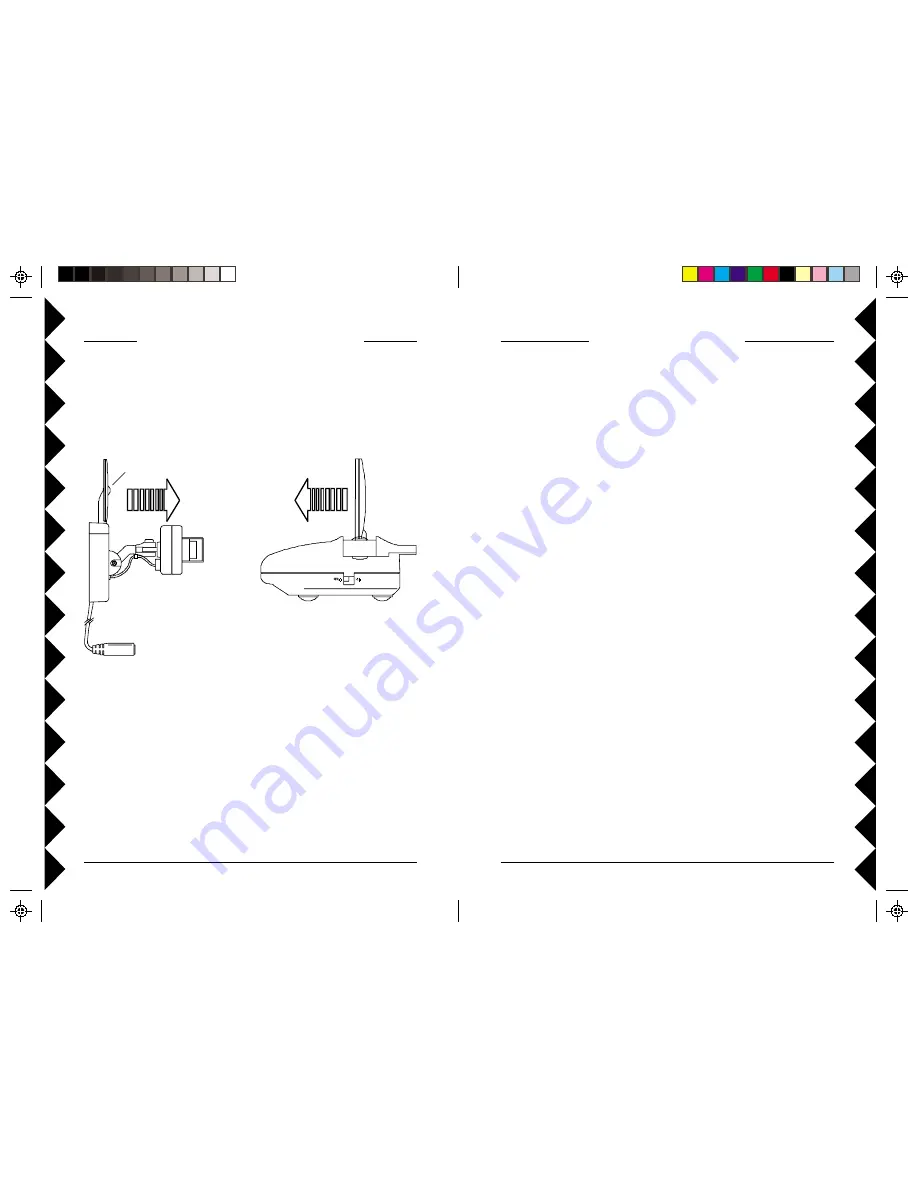
The system usually works best with the "pip" on the Camera's antenna
facing the flat side of the Receiver's antenna (see diagram below).
Sometimes, however, reflections and other effects in the home may affect
the signal so that some adjustment of either the Camera or Receiver
antenna may be necessary to get the best the signal. If you have more than
one Camera, sometimes pointing the Receiver's antenna up towards the
ceiling works best.
I
F
YOU
ARE
NOT
GETTING
ANY
SIGNAL
AT
ALL
Check that the CHANNEL slide switch (labeled A, B, C, D) on both units
(on bottom) is set to the same letter.
If you are using coaxial TV connections from the Video Receiver (Model
VR31A only), check that the TV is tuned to the same channel as the TV
Channel switch on the bottom of the Video Receiver (3 or 4).
Check that the camera's remote controlled power supply is turned on (using
any X10 remote control, sold separately). Note, when you first plug the
power supply in, it will normally be ON.
I
F
THE
SIGNAL
IS
POOR
,
OR
THERE
IS
INTERFERENCE
Try changing the channel on both units. Do this by adjusting the
CHANNEL slide switch on each unit to any position (A, B, C, or D). Make
sure both units are set to the same letter.
T
ROUBLESHOOTING
I
F
YOU
DO
NOT
SEE
A
PICTURE
ON
YOUR
TV:
Check that the Receiver and the Camera are on the same letter channel (A,
B, C, or D). On the Receiver the switch is on the bottom. On the Camera the
switch is located under the rubber plug on the base of the unit. Make sure you
replace the plug afterwards if you intend to use the camera outdoors.
There is a power light on the front of the Receiver. Check that the power
switch on the side of the Receiver is ON.
Check that the Camera is turned on. For single camera systems the power
supply for the Camera will normally be on (it powers up on). For Multi-Camera
systems you need to purchase a TM751 Transceiver for the remote control to
be able to turn Cameras on. When you turn any one on, in a group of 4 on, the
others in the group turn off. Groups must be 1-4, 5-8, 9-12, or 13-16. Check
that all camera power supplies are set to the same Housecode as the Transceiver
and remote control.
Verify that your connections to the TV are correct. If you are using the RCA
jacks, make sure you are using the appropriate input mode for your TV, try
pressing the A-B button or Video button on your TV's remote control to change
the input mode (consult your TV's owner's manual, if necessary). If you are
using a Coax cable (Model VR31A Receiver only), verify that the Receiver
and the TV are on the same channel (3 or 4).
If you connected the Receiver to a VCR and then connected the VCR to your
TV, you might need to turn the VCR OFF to see the Camera's picture on your
TV. Or you might need to turn the VCR on, AND set it to record the picture
from the Camera, in order to see the picture on your TV. Or you might need to
press the A-B button on your VCR's remote control. Consult your VCR's
owner's manual from more information.
I
F
YOU
GET
A
PICTURE
BUT
THE
QUALITY
IS
POOR
:
Try different positions for the antennas on the Camera and Receiver. Normally
they should point at each other. Sometimes, due to reflections, you might get a
better picture with the Receiver's antenna pointing to the ceiling.
Take a look at what the video signal is passing through or near to get to the
Receiver. Metal objects and electromagnetic fields can distort the signal. Try
to keep the Receiver as far away from other devices as the cables allow.


