background image


X-FIT 7 MOTORIZED TREADMILL 


11

ASSEMBLY 


STEP 1

:


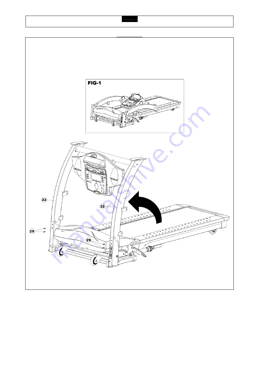
Remove your treadmill from the carton and place it on the floor in an open area as shown in FIG-1. 
 
Rotate the Left Upright (32) and Right Upright (33) up to the correct position as shown and secure in place using four 

M8 x 16mm Allen Bolts

 (29).


Summary of Contents for X-FIT 7

Page 1: ...USER S MANUAL X FIT 7 MOTORIZED TREADMILL MODEL NUMBER X FIT 7 USER WEIGHT LIMITATION 136kgs 300lbs SERIAL NUMBER found on frame 2 rd Edition...

Page 2: ...more than one person on the treadmill at a time Wear appropriate exercise clothing when using the treadmill Do not wear loose clothing that could become caught in the treadmill Athletic support cloth...

Page 3: ...not included with your treadmill Surge protectors can be purchased at most hardware stores The manufacturer recommends a single outlet surge protector with a UL 1449 rating as a Transient Voltage Sur...

Page 4: ...embly quick and hassle free Clear your work area Make sure that you have cleared away a large enough space to properly assemble the unit Make sure the space is free from anything that may cause injury...

Page 5: ...be a few spare parts 2 part 19 and 4 part 10 pieces to be used if needed NO DESCRIPTION QTY 10 M6 x 20mm Allen Head Bolt 4 13 M8 x 10mm Bolt 4 18 8 x 25mm Screw 14 19 8 x 19mm Screw 12 27 1 2 x 68mm B...

Page 6: ...Bolt 2 XFIT7 41 13 M8 x 10mm Bolt 4 XFIT7 13 42 M14 x 113 Bolt 2 XFIT7 42 14 Handlebar Rear End Cap Left 1 1 XFIT7 14 43 Bushing 4 XFIT7 43 15 Handlebar Rear End Cap Left 2 1 XFIT7 15 44 Power Switch...

Page 7: ...Bolt 8 XFIT7 95 69 Running Deck 1 XFIT7 69 96 Elevation Support Tube Clamp upper 2 XFIT7 96 70 Deck Rubber Cushion 10 XFIT7 70 97 Elevation Support Tube Clamp Bottom 2 XFIT7 97 71 Spring Washer 12 XFI...

Page 8: ...T7 117 118 Brush Fixing Bracket Upper 2 XFIT7 118 119 Transport Wheel 2 XFIT7 119 120 M10 x 60mm Bolt 2 XFIT7 120 121 Brush Fixing Bracket Bottom 1 XFIT7 121 122 4 x 19mm screw 6 XFIT7 122 123 M6 x 15...

Page 9: ...X FIT 7 MOTORIZED TREADMILL 9 PARTS DIAGRAM A MAJORITY OF THE PARTS SHOWN HERE HAVE BEEN PREASSEMBLED AT THE FACTORY...

Page 10: ...X FIT 7 MOTORIZED TREADMILL 10 PARTS DIAGRAM A MAJORITY OF THE PARTS SHOWN HERE HAVE BEEN PREASSEMBLED AT THE FACTORY...

Page 11: ...EP 1 Remove your treadmill from the carton and place it on the floor in an open area as shown in FIG 1 Rotate the Left Upright 32 and Right Upright 33 up to the correct position as shown and secure in...

Page 12: ...move the four M6 x 20mm Allen Head Bolts 10 from the back of the Bottom Console Housing 3 they have been preassembled by the factory Then secure the Bottom Console Housing 3 to the Console Support Tub...

Page 13: ...X FIT 7 MOTORIZED TREADMILL 13 ASSEMBLY STEP 3 Attach a Plastic Cover 40 to the Left Upright 32 and to the Right Upright 33 then secure each in place using one M6 x 15mm Phillip Head Screw 58...

Page 14: ...Tube Assembly 36 to the Left Upright 32 and secure with Upright Support Lock Pin 30 and M6 x 15 Allen Head Screw 31 Repeat the procedure on the Right Upright 33 Note Turn the Connector Bolt 37 as show...

Page 15: ...ORIZED TREADMILL 15 ASSEMBLY STEP 5 Rotate up the Suspension System Hardware Assembly 34 and secure to the Left Upright 32 using Bolt 27 Rubber Spacers 28 and Nut 29 Repeat this procedure on the Right...

Page 16: ...e 11 then rotate the Console Support Tube 11 up to the correct position as shown and secure it in place using the M5 x 12 Screw 12 Attach the Glove Compartment 6 to the Top Console Housing 2 and secur...

Page 17: ...1 52 to the Upright Plastic Shroud Left 2 53 and Left Upright 32 using six 8 x 25mm Screws 18 and four 8 x 19mm Screws 19 Attach the Upright Plastic Shroud Right 1 55 to the Upright Plastic Shroud Rig...

Page 18: ...the two sets of wires between the Handlebar 133 and the Left Upright 32 as shown in FIG 5 Attach the Handlebar 133 to the Left Upright 32 using two M8 x 10mm Bolts 13 Repeat this procedure on the othe...

Page 19: ...andlebar Rear End Cap Left 2 15 to the top of the Left Upright 32 using two 8 x 25mm Screws 18 and two 8 x 19mm Screws 19 Attach the Handlebar Rear End Cap Right 2 16 and Handlebar Rear End Cap Right...

Page 20: ...nt Handlebar 130 to the Console Support Tube 11 and secure with two M8 x 25mm Bolts 99 Your X Fit 7 treadmill is now fully assembled NOTE Please make sure the Safety Key is inserted it is located belo...

Page 21: ...sit firmly on the floor to prevent the treadmill from wobbling during use 2 Inspect the two stabilizers one per side and two installed casters one per side located underneath the base frame The treadm...

Page 22: ...X FIT 7 MOTORIZED TREADMILL 22 TRANSPORTATION INSTRUCTIONS How to transport your treadmill To move your treadmill simply lift the rear of the deck and roll it to the desired location...

Page 23: ...with a test If your belt continues to walk to the right simply adjust the left belt tension bolt by turning it 1 4 turn counterclockwise and follow with a test 2 If your belt tends to walk to the lef...

Page 24: ...t for 1 minute before using the treadmill Spray lubricant from front to back CLEANING Routine cleaning of your treadmill will extend the product s life Warning To prevent electrical shock be sure the...

Page 25: ...e only for a few minutes in your target heart rate zone However your aerobic fitness will improve over the next six to eight weeks Don t be discouraged if it takes longer It s important to work at you...

Page 26: ...ysical condition To determine your target zone consult the chart we have provided FIND YOUR TARGET HEART RATE 200 180 160 140 120 100 HEART RATE in beats per minute 80 20 25 30 35 40 45 50 55 60 65 70...

Page 27: ...ll develop primarily lower body muscle groups These muscle groups are shown in gray color on the chart below Shoulder muscles A B Pectoral muscles Bicep muscle C D Abdominal muscles Forearm muscles E...

Page 28: ...muscles At the end of your workout repeat these exercises to reduce sore muscle problems We suggest the warm up and cool down exercises on the following pages Toe Touch Slowly bend forward from your w...

Page 29: ...ssible Gently push your knees towards the floor Hold for 15 counts Side Stretch Open your arms to the side and continue lifting them until they are over your head Reach your right arm as far upward to...

Page 30: ...Copyright 2003...

Reviews: