9
Technical Support: [email protected] US: +1 866 677 0053 EU: +44 (0) 1793 230 343
UPDA
TING RS232 SETTINGS AND RS232 CONNECTION
RS-232 Logic Waveform (8N1)
The graphic (bottom left) illustrates a typical RS232 logic waveform (Data format: 1 Start bit, 8 Data bits, No Parity, 1
Stop bit). The data transmission starts with a Start bit, followed by the data bits (LSB sent first and MSB sent last), and
ends with a “Stop” bit.
The voltage of Logic “1” (Mark) is between -3VDC to -15VDC, while the Logic “0” (Space) is b3VDC to
+15VDC.
RS232 connects the Ground of 2 different devices together, which is the so-called “Unbalanced” connection. An
unbalanced connection is more susceptible to noise, and has a distance limitation of 15m/49ft.
9. Updating RS232
Settings
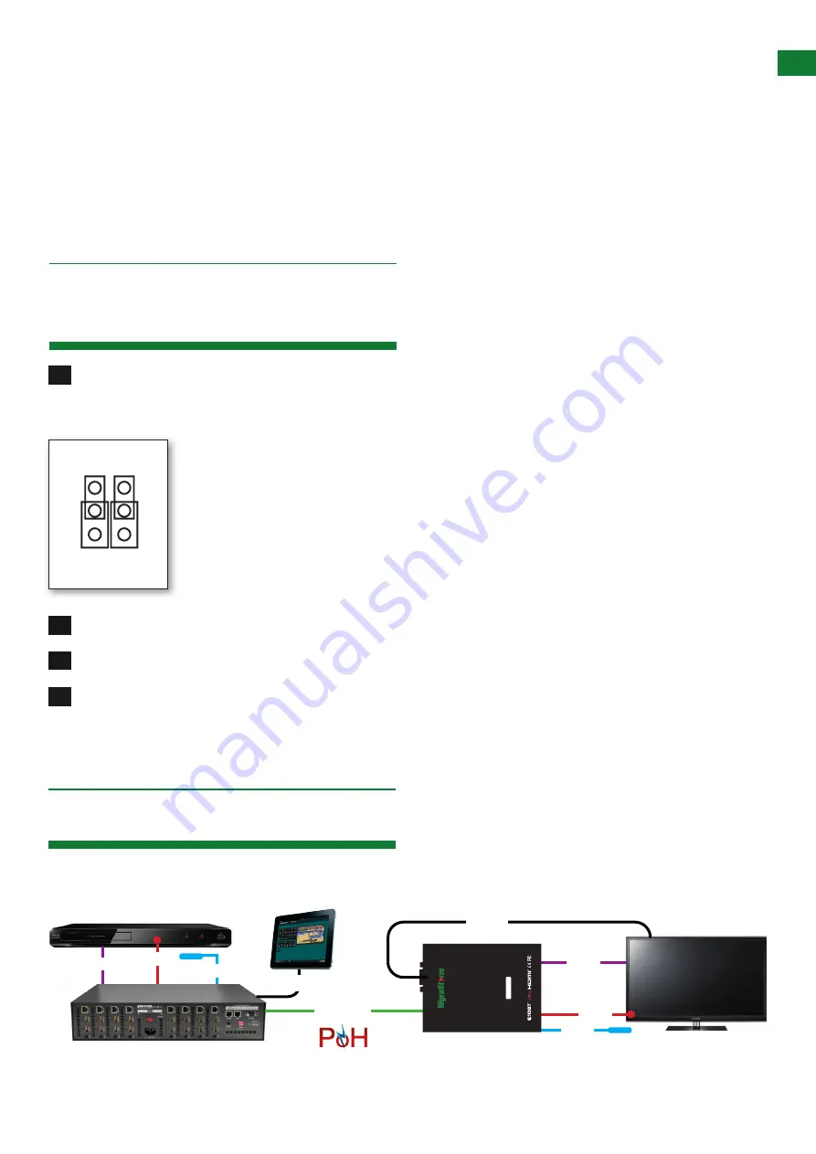
10. RS232 Connection
Carefully open the case of the EX-70-IR-PP-POH Receiver. On the edge of the circuit board are positioned two
jumper caps to change settings from the ‘Normal’ position for default operation to ‘Update’, which allows
the system to enter
Firmware Update Mode
Gently move the jumper caps to the ‘Update’ position to allow upgrade through the RS232 port.
Connect USB - Serial Cable to PC and run VS010 RX Firmware Update batch file.
Once update has been completed, be sure to return the jumper caps to the ‘Normal’ position for RS232 control
signal transmission to be passed.
Note:
Connect RS232 cables to the RS232 port of the EX-70-IR-PP-POH Receiver to form one extension cable.
To allow serial commands sent from transmitting device to be sent to display device, simply connect a 9 pin straight
through RS232 cable between the RX-70-IR-POH and your display.
1
2
3
4
Update
Normal
1
3
4
2
5
6
hdmi
ir rx
ir tx
cat5e/6
70m/230ft
rs232
HDMI
hdmi
ir rx
ir tx
re
ceive
r
RX70-IR-P
P-
PO
H
70m/230ft HDMI Extension over HDBaseT
3D compatible, Bidir
ectional IR, Powe
r-ove
r-HDBaseT
rs232


