6. To repeat the indoor system checkout before installation, switch power OFF to the
LDR to effect a complete LDR reset. Check the fiber-optic cable connections and
ensure that the fiber is fully seated in the fiber-optic transmitter on the Sensor and
fully seated in the fiber-optic receiver on the Lightning Data Receiver. Now
repeat Step 5. When normal system function is verified, install the system.
Leave all equipment as is and go to Step 7.
7. Refer to the RS-232 to Fiber-optic Converter (the “Converter”) User Guide and
install the Converter on an unused RS-232 communications port of a computer.
The Converter has a 9-socket (female) connector that will mate directly to any 9-
pin D subminiature connector such as the COM1 or COM2 or other serial ports
on a computer. A short, straight-through (NOT null-modem) adapter cable may
be used to mount the Converter to a serial port on a computer.
NOTE
If an RS-232 port is not available and the computer has only USB
serial communications ports, refer to the Strike View Software
User’s Guide for instructions on installation of a USB to RS-232
Adapter.
8. Follow the Strike View installation procedures as outlined in the Strike View
Software User’s Guide or in the Quick Reference Guide in Section 9 of this guide.
Once the computer is restarted after installation, initiate the Strike View Software
application. Connect the fiber-optic cable supplied with Strike View Software
between the blue FIBER OUT port of the Lightning Data Receiver and the black
FIBER IN port of the RS-232 to Fiber-optic Converter using the same techniques
for proper fiber-optic cable connections described in Section 3-E. Ensure that the
ends of the fiber are fully seated in the fiber-optic devices. When the Strike View
application is running the system is ready to be tested.
9. With the Lightning Data Receiver turned ON and with Strike View Software
running and with all fiber-optic connections in place, pick up the Strike Guard
Lightning Sensor and turn it UPSIDE DOWN for at least 10 seconds. Now turn
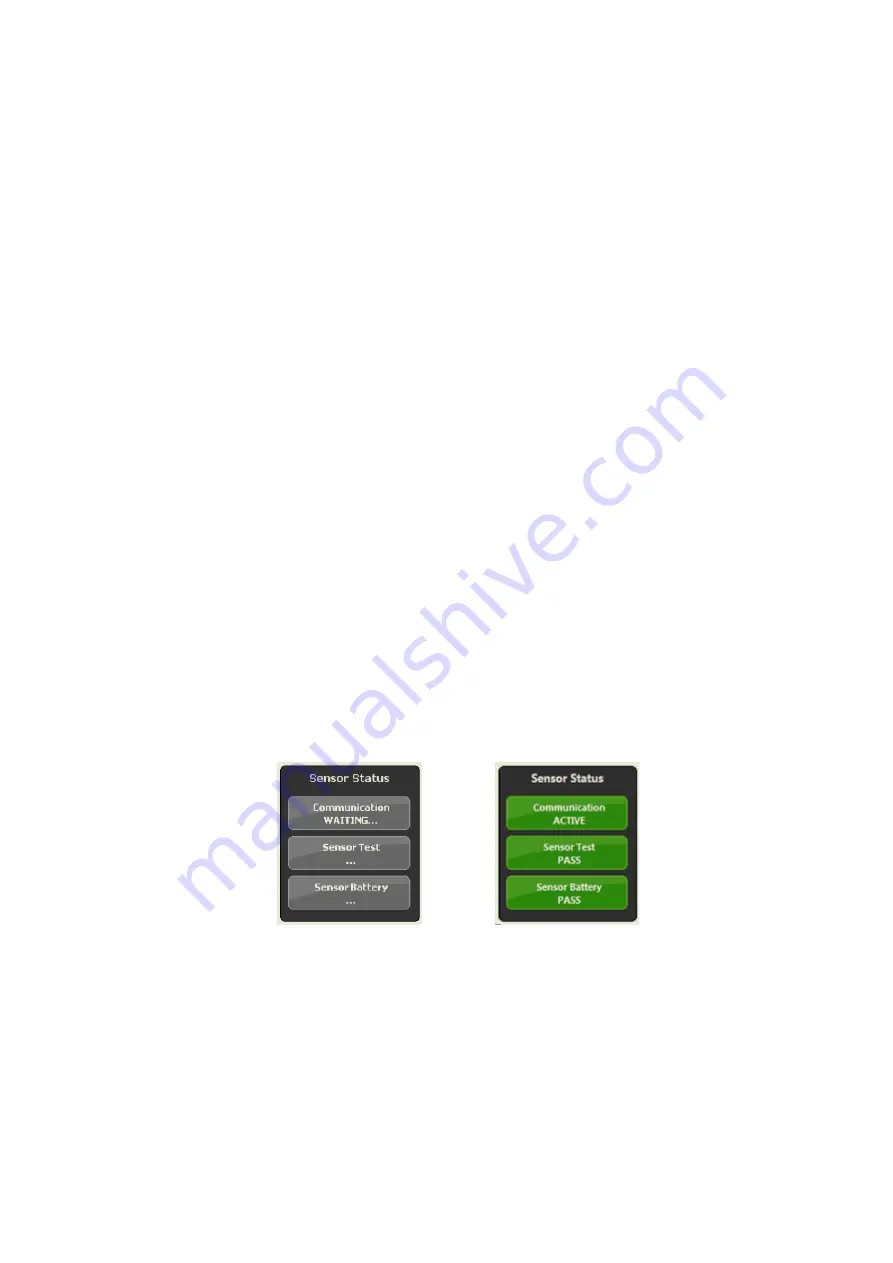
the Sensor right side up and set it on the desktop. Note that the status window in
the lower right hand corner of the Strike View Software screen changes with the
receipt of the first status messages from the Sensor.
Look for the screen area in the lower right hand corner to change from:
10. If all results are normal to this point, then proceed to the selection of an
appropriate site for the Sensor.
Strike Guard Lightning Warning System
9
DEC 2013
Summary of Contents for Strike Guard
Page 32: ...Strike Guard Lightning Warning System 32 DEC 2013 ...
Page 33: ...Strike Guard Lightning Warning System 33 DEC 2013 ...
Page 34: ...Strike Guard Lightning Warning System 34 DEC 2013 ...
Page 35: ...Strike Guard Lightning Warning System 35 DEC 2013 ...
Page 36: ...Strike Guard Lightning Warning System 36 DEC 2013 ...
Page 37: ...Strike Guard Lightning Warning System 37 DEC 2013 ...


