Installation, Oper ation & M aintenance M anual
TR-C Series Centrifugal Pump
13
TR-C-
M02
The seal will provide a resistance when it slides on, so apply pressure until it has gone onto
the stub shaft completely. The position of the drive collar against the o-ring and carbon is
critical to prevent leaks. Now, assemble the
“D” seal backplate (
11
) and fix it with the backplate
pins. Push the carbon back with the backplate.
Once the backplate has been placed it is necessary to tighten the “D” seal collar set screws
(
80L
). To do this, you must exert a pressure on the drive collar towards the backplate, so
that the pin of the drive collar remains aligned with the slot in the cup.
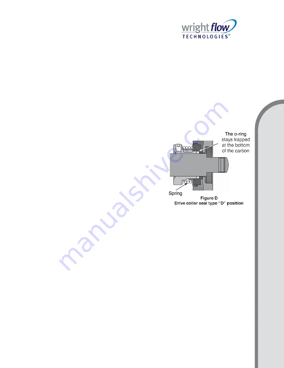
Tighten the set screws once the drive collar has reached its closest point to the o-ring and
carbon. The drive collar should stay in its place against the o-ring
– against the back – within
the limits of the carbon, as shown in
Figure D.
The spring does not
compress entirely.
When all parts are in their correct positions, the stub shaft
should be able to rotate freely when turned by hand. If it is
necessary to use excessive force to turn the stub shaft, check
to be sure that the components of the seal have been properly
installed and that the drive collar is properly positioned.
The “F” seal is the “D” seal with a water-cascade assembly.
The water-cascade assembly (
132
) should be installed on
the adapter (
71
), so that the leak falls upon the seal seat of
the carbon, lubricating the seal against the backplate.
IMPORTANT:
It is necessary to disassemble some of the
pump parts for cleaning and
sterilizing. For those Wright Flow
products equipped with “D” seals, if a CIP (Clean-in-Place)
installation is used, disassembly is not necessary. Do not lubricate the seal with grease or oil,
the faces of the seals are lubricated by the fluid that is being pumped.
CLAMPED-IN SEAT SEAL TY
PE “DG”.
This seal type consists of two parts: one
stationary, and one rotating. The rotating part is the
“D” seal assembly. For that reason, it is
highly recommended that you read the directions above for assembling the
“D” seal before
continuing. The stationary part consists of the following elements:
“DG” seal seat (
80N
), PTFE
gasket (
80P
), PTFE gasket (
80R
), “DG” gland ring (
17J
), lock washers (
17M
), bolts/screws
gland ring (
17K
),
and “DG” seal backplate (
11H
).
IMPORTANT:
Incorrect spacing between the impeller and backplate can result in dangerous
contact between the impeller and the face of the stationary seal. That contact may wear down
the impeller and the seat of the gland ring. A visual inspection following the installation of the
impeller is recommended to check the spacing of the impeller and seal.
Take
the “DG” backplate (
11H
), turn it around and place the PTFE gasket (
80R
) against the
seal face. Next, install the seal seat (
80N
)
– which is reversible – followed by the PTFE gasket
(
80P
) and finally the gland ring (
17J
). In the seal type
“DG”, the seal seat (
80N
) is enclosed by
the gland ring, which could be made of either silicone, tungsten, or ceramic
A
SS
EM
B
LY


