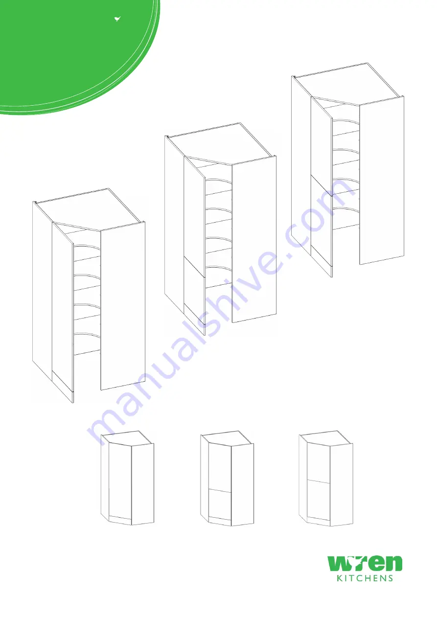
TOWER UNIT
2070 & 2250 Walk in
Assembly Guide
For Internal Use: FI.WR.INS.014_WKIN0062_WalkIn_TowerGuide_Rev12.indd
2070 - 2250 x600
1 Door
50/50 Door
70/30 Door
Page 1: ...TOWER UNIT 2070 2250 Walk in Assembly Guide For Internal Use FI WR INS 014_WKIN0062_WalkIn_TowerGuide_Rev12 indd 2070 2250 x600 1 Door 50 50 Door 70 30 Door ...
Page 2: ...anel B x1 End Panel Right Hand Panel C x1 Back Panel Left Hand Panel D x1 Back Panel Right Hand Panel sE x1 Top Panel Panel sM x4 Fixed Shelf Frontals 50 50 or 1Dr or 70 30 Packed Seperately Plinth x1 L Bracket LGE x4 Fixing Plate U x4 Hinge Mounting Plate Inc Screws Hinge Inc Screws F x40 Wooden Dowel H x20 Cam lock NOT to be used with CAM DOWEL CAM LOCK K x36 45mm Screws L x12 15mm Screws REQUIR...
Page 3: ...to holes in end panel A as shown sM sM sM sM sE A Step 4 Join panels sE and sM to end panel A Insert cam locks H Do NOT tighten until Step 7 Do not use power tools with cam dowel G or cam lock H Step 3 Attach panels sM and sE to end panel A using cam dowel W in blue and also using dowels F in orange in positions as shown sM sM A View from underside View from underside A H H A LH from top from bott...
Page 4: ...e back panel C to panels sM and sE Step 9 Secure back panel C to end panel A at the bottom Use 4 x 15mm screws L to 1 x L bracket LGE as shown Step 6 Slide back panel C into groove of end panel A Also insert dowels F in orange from panels sM and sE into the required holes in back panel C Once back panel C is in position ensure the panel is flush square with bottom of end panel A L C L L L A LH A s...
Page 5: ...at W cam dowel into hole as shown Do not use power tools with cam dowel G or cam lock H Step 12 Attach end panel B to panels sM and sE using cam dowel W in blue and also using dowels F in orange in positions as shown F F RIGHT HAND B W W from bottom from top DOWEL F CAM DOWEL W LOCATION DETAIL Step 13 Join panels sE and sM to end panel A Insert cam locks H Do NOT tighten until Step 18 F W sM sM Vi...
Page 6: ...indd Page 5 Step 14 Seat 10x dowels F into holes in both panels sM and sE as shown sM sM sM sM sE F Step 15 Secure back panel D to panels sE and sM and back panel C Use 20 x 45mm screws K as shown Step 16 Ensure to insert the lower position of back panel D into end panel B groove K A B RH LH C D C B RH LH B D ...
Page 7: ...locks H this will expand cam dowels W and tighten the unit together D M View from underside B H Step 19 Secure tower to the wall using L brackets LGE Use 2 x 15mm screws L to secure each of the L brackets LGE to the cabinets at either side Then screw through into the wall as shown Screws for fixing to walls are not provided as these vary depending on your wall material and construction Ensure appr...
Page 8: ...N A or B A or B 1976mm 1976mm 1236mm 1016mm 996mm 1486mm 776mm 276mm 276mm 1944mm 1944mm 1204mm 984mm 964mm 1454mm 744mm 244mm 244mm Step 20 Attach hinge plates onto end panel A or B to suit as shown Hinge side to be mounted in accordance to customer kitchen plan Front Front From Top From Top From Bottom From Bottom 50 50 70 30 1 Dr Door INSIDE FACE INSIDE FACE ...
Page 9: ...r B A or B 2156mm 2156mm 1176mm 1666mm 996mm 1576mm 776mm 276mm 276mm 956mm 2124mm 2124mm 1144mm 1634mm 964mm 1544mm 744mm 244mm 244mm 924mm Step 20 Attach hinge plates onto end panel A or B to suit as shown Hinge side to be mounted in accordance to customer kitchen plan Front Front From Top From Top From Bottom From Bottom 50 50 70 30 INSIDE FACE INSIDE FACE ...
Page 10: ...in Assembly Guide 1 Door HINGE POSITION 2156mm 1351 5mm 1080 5mm 1319 5mm 1048 5mm 276mm 2124mm 244mm Step 20 Attach hinge plates onto end panel A or B to suit as shown Hinge side to be mounted in accordance to customer kitchen plan Front From Top From Bottom 1 Dr Door A or B INSIDE FACE Page 9 ...
Page 11: ...RENGTH Hinge Cover Caps Hinge Plates Step 25 Fit cover caps to hinge Adjust soft close to suit The Top and Bottom hinges MUST be adjusted to the SAME STRENGTH Step 22 Align doors frontal plinth to join together using 4 x fixing plates U to the back of both frontals Ensure a 3mm gap is maintained between each frontal once fixed together Screw in place using 4 x 15mm screws L per fixing plate U See ...
Page 12: ...e to suit The Top and Bottom hinges MUST be adjusted to the SAME STRENGTH Hinge Plates Step 23 Attach the door to unit clip hinge onto hinge plate and click to secure Step 21 Insert hinge into hinge holes provided To adjust hinge using a screw driver tighten or loosen as required at points 1 2 Point 1 In Out Point 2 Left Right To release door pull catch as shown doing so will release the hinge fro...