background image

TECHNICAL DATA 10

21

10.1

Fork

Fork article number

34.18.2T.07

Fork

XACT PRO 7448

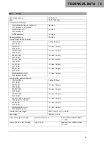
Compression damping

125/150/250 SX EU, 450 SX

F EU

TC 125/250 EU, FC 450 EU

18 clicks

250/350 SX

F EU

FC 250/350 EU

14 clicks

All US versions

15 clicks

Rebound damping

20 clicks

Air pressure, positive chamber

125/150 SX EU
TC 125 EU

8.6 bar (125 psi)

250 SX EU
TC 250 EU

10.0 bar (145 psi)

250 SX

F EU

FC 250 EU

10.6 bar (154 psi)

350 SX

F EU

FC 350 EU

10.8 bar (157 psi)

450 SX

F EU

FC 450 EU

10.5 bar (152 psi)

125 SX US
TC 125 US

10.3 bar (149 psi)

250 SX US
TC 250 US

11.3 bar (164 psi)

250/350/450 SX

F US

FC 250/350/450 US

11.5 bar (167 psi)

Air pressure, negative chamber

125/150 SX EU
TC 125 EU

9.6 bar (139 psi)

250 SX EU
TC 250 EU

11.0 bar (160 psi)

250 SX

F EU

FC 250 EU

10.6 bar (154 psi)

350 SX

F EU

FC 350 EU

10.8 bar (157 psi)

450 SX

F EU, 125 SX US

FC 450 EU, TC 125 US

11.5 bar (167 psi)

250 SX US
TC 250 US

12.5 bar (181 psi)

250/350/450 SX

F US

FC 250/350/450 US

12.7 bar (184 psi)

Visible inner tube length

309 ± 2 mm (12.17 ± 0.08 in)

Fork length

950 mm (37.4 in)

Oil capacity, right cartridge

375 ml (12.68 fl. oz.)

Fork oil (SAE 4) (48601166S1)
(

p. 23)

Grease capacity, left cartridge

5 g (0.18 oz)

Special grease (00062010053)
(

p. 24)

Summary of Contents for XACT PRO 7448

Page 1: ...OWNER S MANUAL XACT PRO 7448 Art no 53000180en http www wp suspension com ...

Page 2: ......

Page 3: ...odify or delete technical specifications prices colors forms materials services designs equipment etc without prior notice and without providing reasons to adapt these to local conditions as well as to stop the production of a particular model without prior notice WP accepts no liability for delivery options deviations from figures and descriptions misprints and other errors The models portrayed p...

Page 4: ...CE SCHEDULE 10 7 1 Additional information 10 7 2 Required work 10 7 3 Recommended work 10 8 SERVICE WORK ON THE CHASSIS 11 8 1 Raising the motorcycle with a lift stand 11 8 2 Removing standard fork legs 11 8 3 Installing the WP PRO COMPONENTS fork legs 11 8 4 Bleeding the fork legs 12 8 5 Cleaning the dust boots of the fork legs 12 8 6 Removing the motorcycle from the lift stand 13 9 TUNING THE CH...

Page 5: ...ith the optimum care and attention by specially trained experts using the necessary special tools Indicates a page reference more information is provided on the specified page Indicates information with more details or tips Indicates the result of a testing step Indicates the end of an activity including potential rework 1 2 Formats used The typographical formats used in this document are explaine...

Page 6: ... at the relevant passages Info Various information and warning labels are attached in prominent locations on the product described Do not remove any information or warning labels If they are missing you or others may not recognize dangers and may therefore be injured 2 4 Degrees of risk and symbols Danger Identifies a danger that will immediately and invariably lead to fatal or serious permanent i...

Page 7: ...tions of the respective country 2 8 Owner s Manual It is important that you read this Owner s Manual carefully and completely before making your first trip The Owner s Manual contains useful information and many tips on how to operate handle and service your motor cycle This is the only way for you to find out how to set up the chassis component ideally and how to protect yourself from injury Keep...

Page 8: ...vice care and tuning work is properly carried out as described in the Owner s Manual Incorrect adjustment and tuning of the chassis and suspension can lead to damage and breakage of components Use of the chassis component under difficult conditions such as on sand or on wet and muddy surfaces can lead to considerably more rapid wear For this reason it may be necessary to inspect or replace parts b...

Page 9: ...S 4 7 4 1 Fork article number 401947 10 The fork article number 1 is stamped on the inside of the axle clamp Info The fork article number consists of an eight figure number with a single letter in the sixth position ...

Page 10: ... and overload components Only make adjustments within the recommended range Ride slowly to start with after making adjustments to get the feel of the new handling characteristic Adjust the compression damping of the fork p 14 Adjust the rebound damping of the fork p 15 Set the fork air pressure of the positive chamber p 15 Set the fork air pressure of the negative chamber p 18 Set the fork air pre...

Page 11: ...ndition of the chassis component and ensure that it is safe to operate The chassis must be in perfect technical condition when it is being operated H02539 01 Check chassis component for damage Clean the dust boots of the fork legs p 12 Bleed the fork legs p 12 Check all screw connections to ensure that they are tight ...

Page 12: ...ded work must be ordered sepa rately and can be invoiced separately Different service intervals may apply in your country depending on the local operating conditions 7 2 Required work Every 40 operating hours Service the fork Periodic interval 7 3 Recommended work After 10 operating hours Service the fork One time interval ...

Page 13: ...her wheel is in contact with the ground Secure the motorcycle against falling over 8 2 Removing standard fork legs H03150 10 Remove the standard fork legs as per the instructions of the vehicle manufacturer 8 3 Installing the WP PRO COMPONENTS fork legs M01743 10 Install the fork legs in accordance with the instructions of the vehicle manufacturer Bleeder screws 1 are positioned toward the front T...

Page 14: ...dust boots of the fork legs Preparatory work Raise the motorcycle with a lift stand p 11 Remove the fork protector M01745 10 Main work Push dust boots 1 of both fork legs downward Info The dust boots remove dust and coarse dirt parti cles from the inside fork tubes Over time dirt can accumulate behind the dust boots If this dirt is not removed the oil seals behind can start to leak Warning Danger ...

Page 15: ...e lift stand p 13 8 6 Removing the motorcycle from the lift stand Note Danger of damage The parked vehicle can roll away or fall over Park the vehicle on a firm and level surface H03151 01 Remove the motorcycle from the lift stand as per the instruc tions of the vehicle manufacturer Remove the lift stand ...

Page 16: ... basic setting of the fork Info For various reasons no exact riding sag can be determined for the fork 401000 01 Weight differences can be compensated for by changing the fork air pressure However if the fork frequently bottoms out hard end stop on compression the fork air pressure must be increased within the specified values to avoid damage to the fork and frame If the fork feels unusually hard ...

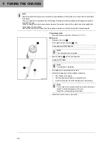
Page 17: ...ower end of the right fork leg Turn counterclockwise by the number of clicks correspond ing to the fork type Guideline Rebound damping 20 clicks Info Turn clockwise to increase the damping turn counterclockwise to reduce damping when the shock absorber rebounds Mount protection cap 1 9 5 Setting the fork air pressure of the positive chamber Warning Danger of accident Modifications to the suspensio...

Page 18: ...tive chamber again Preparatory work Raise the motorcycle with a lift stand p 11 M01748 10 Main work Remove valve cap 1 Push together fork airpump 2 fully Fork airpump 79412966100 Info The fork airpump is included Mount adapter 3 on the fork airpump Adapter T14086E Info The adapter is included The adapter is connected to the valve Rotate the upper part of the adapter clockwise The interior valve op...

Page 19: ...e in steps of 0 05 0 1 bar 0 7 1 psi Minimum air pressure 5 bar 73 psi Maximum air pressure 15 bar 218 psi Info Never adjust the air pressure to a value outside the stated range Rotate the upper part of the adapter anticlockwise The interior valve closes Disconnect the adapter from the left fork leg When disconnecting excess pressure will escape from the hose the fork leg does not lose any air The...

Page 20: ... the air pressure always observe the correct value of the visible inner tube length and only proceed in small steps First set the positive chamber then the negative chamber and finally the positive chamber again Preparatory work Raise the motorcycle with a lift stand p 11 Set the fork air pressure of the positive chamber p 15 M01749 10 Main work Remove protection cap 1 Remove screw cap 2 Push toge...

Page 21: ...bar 73 psi Maximum air pressure 15 bar 218 psi Info Never adjust the air pressure to a value outside the stated range Rotate the upper part of the adapter anticlockwise The interior valve closes Disconnect the adapter from the left fork leg When disconnecting excess pressure will escape from the hose the fork leg does not lose any air The fork pump airpump switches off automatically after 80 secon...

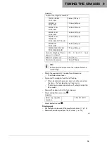
Page 22: ...vel is reduced If the length is too long the bending moment and wear are increased Preparatory work Raise the motorcycle with a lift stand p 11 M01750 10 Main work Measure visible inner tube length A Visible inner tube length 309 2 mm 12 17 0 08 in If the visible inner tube length does not correspond to specifications Set the fork air pressure of the positive chamber p 15 Set the fork air pressure...

Page 23: ...X US TC 125 US 10 3 bar 149 psi 250 SX US TC 250 US 11 3 bar 164 psi 250 350 450 SX F US FC 250 350 450 US 11 5 bar 167 psi Air pressure negative chamber 125 150 SX EU TC 125 EU 9 6 bar 139 psi 250 SX EU TC 250 EU 11 0 bar 160 psi 250 SX F EU FC 250 EU 10 6 bar 154 psi 350 SX F EU FC 350 EU 10 8 bar 157 psi 450 SX F EU 125 SX US FC 450 EU TC 125 US 11 5 bar 167 psi 250 SX US TC 250 US 12 5 bar 181...

Page 24: ...50 350 EU Oil capacity external mechanism right 270 30 70 ml 9 13 1 01 2 37 fl oz Fork oil SAE 4 48601166S1 p 23 125 150 250 SX EU 450 SX F EU 125 250 SX US 250 350 450 SX F US TC 125 250 EU FC 450 EU TC 125 250 US FC 250 350 450 US Oil capacity external mechanism left 240 60 40 ml 8 11 2 03 1 35 fl oz Fork oil SAE 4 48601166S1 p 23 250 350 SX F EU FC 250 350 EU Oil capacity external mechanism lef...

Page 25: ... 23 Fork oil SAE 4 48601166S1 Standard classification SAE p 25 SAE 4 Guideline Use only oils that comply with the specified standards see specifications on the container and that exhibit the corresponding properties ...

Page 26: ...12 AUXILIARY SUBSTANCES 24 Special grease 00062010053 Recommended supplier Klüber Lubrication KLÜBERFOOD NH1 34 401 ...

Page 27: ... The SAE viscosity classes were defined by the Society of Automotive Engineers and are used for classifying oils according to their viscosity The viscosity describes only one property of oil and says nothing about quality ...

Page 28: ...14 LIST OF ABBREVIATIONS 26 Art no Article number ca circa cf compare e g for example etc et cetera i a inter alia no number poss possibly ...

Page 29: ...ing 15 visible inner tube length measuring 20 Fork legs bleeding 12 dust boots cleaning 12 standard version removing 11 WP PRO COMPONENTS version installing 11 Fuel oils etc 6 I Implied warranty 6 Intended use 4 M Misuse 4 Motorcycle lift stand raising with 11 lift stand removing from 13 O Owner s Manual 5 P Preparing for use advice on preparing for first use 8 checks and maintenance measures when...

Page 30: ... 53000180en 53000180en 07 2019 WP Suspension GmbH 5230 Mattighofen Austria http www wp suspension com ...

Reviews: