


14
3 in 1 Grass Trimmer/Edger
EN
15
14
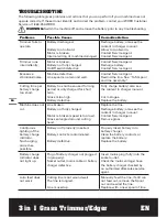
TroUBLEsHooTING
The following table gives problems and actions that you can perform if your machine does not
operate correctly. If these do not identify and correct the problem, contact your WORX Customer
Service at 1-866-354-WORX.
waRNiNG:
Switch the machine off and remove the battery prior to any troubleshooting.
Problems
Possible Causes
Corrective action
Trimmer fails to
operate.
Battery discharged.
Battery too hot/cold.
Motor is broken.
Internal wiring of machine damaged.
Recharge battery; also see the
content in charger manual.
Allow to cool/warm.
Contact Service Agent.
Contact Service Agent.
Trimmer runs
intermittently.
Motor is broken.
Battery not fully charged.
On/Off switch defective.
Contact Service Agent.
Recharge battery.
Contact Service Agent.
Excessive
vibrations/noise.
Machine defective.
Line spool is not wound well.
Contact Service Agent.
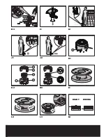
Rewind the line. See ’’ To fit spool
and line assembly.’’
Cutting time per
battery charge
too short.
Battery has not been used for long
period or only charged for short
term.
Grass is too high.
Battery defective.
Fully charge battery; also see
the content in charger manual.
Cut in stages.
Replace the battery.
Machine does not
cut.
Line broken.
Battery not fully charged.
Motor is broken (speed is too low).
Grass entangled around cutting
head.
Replace the line.
Recharge battery; also see the
content in charger manual.
Contact Service Agent.
Remove grass.
Continuous
lighting of the
battery charge
indicator.
No charging
procedure
possible.
Battery not (properly) inserted.
Battery contacts contaminated.
Battery defective.
Properly insert battery into
battery charger.
Clean the battery contacts or
replace the battery.
Replace the battery.
Battery charge
indicator does
not light up.
Plug of battery charger not plugged
in (properly).
Socket outlet, mains cable or battery
charger defective.
Insert mains plug (fully) into the
socket outlet.
Check the mains voltage; have
the battery charger checked by
an authorized after-sales service
agent.
Auto feed does
not work
Cutting line is not wound well.
The line is tangled.
Line is used up.
Manually feed the line, if still can
not feed out, remove the Spool
out and rewind the line.
Replace with a new spool of line.


