

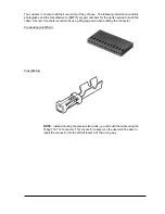


The bracket should be used as a template to mark screw holes for installation. See Figure 4 -
WorldTracker AVL Mounting Brackets. The mounting holes are designed for a number 10 screw.
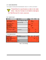
Once mounting holes have been located for placement, the mounting plate can be easily broken into
two parts as demonstrated in Figure 5 - WorldTracker AVL Mounting Bracket (separated). The
mounting bracket must be separated in order to affix it to the WorldTracker AVL. The two pieces will
easily slide into the grooves on the modem.
2.2 Installing Cables
During installation, the following precautions will help ensure proper operation of the WorldTracker AVL
•
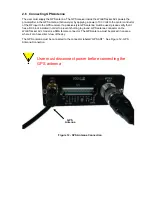
Remove power from the WorldTracker AVL.
•
Do not create loops, sharp bends or crimps in the cables
•
All cables should be attached to the vehicle and equipment in such a way to reduce stress or
wear caused by vibration generated by moving vehicles.
•
Use proper terminations on all power cables
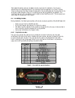
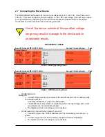
2.2.1 12 pin Connector
The user can purchase the optional 12-pin external I/O connector for the Security Concepts
WorldTracker AVL that can be used to interface with other devices. Security Concepts can provide
an optional cable and connector. The user also has the option of building his/her own cable.
Table 1 describes the pin functionality for this 12 pin I/O connector. Pins that are not planned for
usage can be left open without anything connected to them.
Pin Number
Functionality
Pin – 1
Serial Data Out
Pin – 2
Serial Data In
Pin – 3
Audio – Ear Speaker Out (-)
Pin – 4
Audio – Ear Speaker Out (+)
Pin – 5
Audio – Mic Input (+)
Pin – 6
Audio – Mic Input (-)
Pin – 7
User Controlled Output
Pin – 8
User Controlled I/O
Pin – 9
User Controlled I/O
Pin – 10
Switched Power (Ignition)
Pin – 11
Unswitched Power (Battery)
Pin – 12
Ground
Table 1 - 12 pin I/O Connector Interface
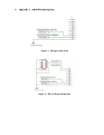
Figure 8 - I/O
Connector


