


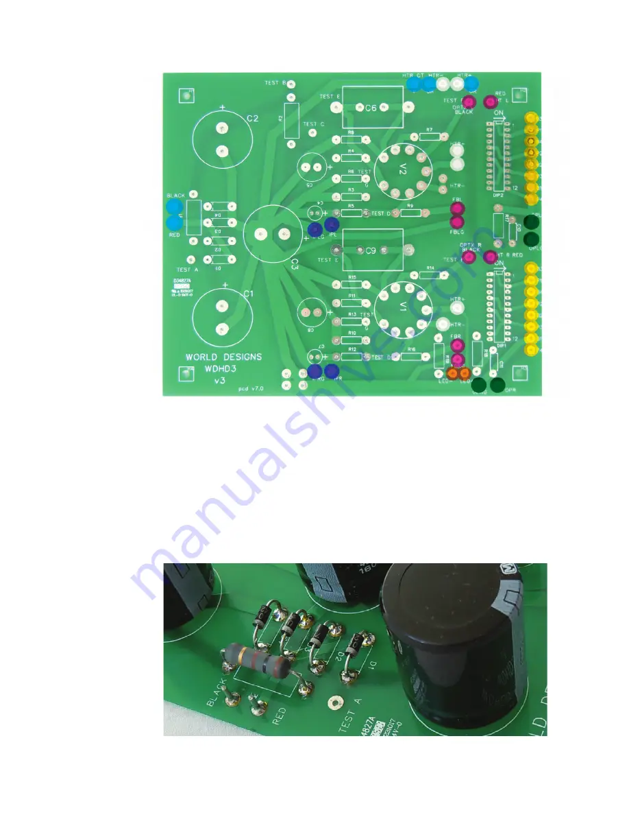
Fig. 8
Diode Polarity
Fig. 7
PCB Pin and Heater Link Positions
8
WDHD3S Kit Assembly Instructions
FIT THE DIODES.
Fit the diodes D1, D2, D3 & D4. Orientation is very important
-
note that the stripe on the diode matches with the stripe on the
PCB legend for correct polarity.
FIT THE RESISTORS.
Elevate the higher power resistors R1, R2, R4, R6, R11, R13,
R17, R18, R19 from the PCB by at least 10mm as they require a
cooling flow of air around them.
Figs.
8 / 10
Fig. 10


