5
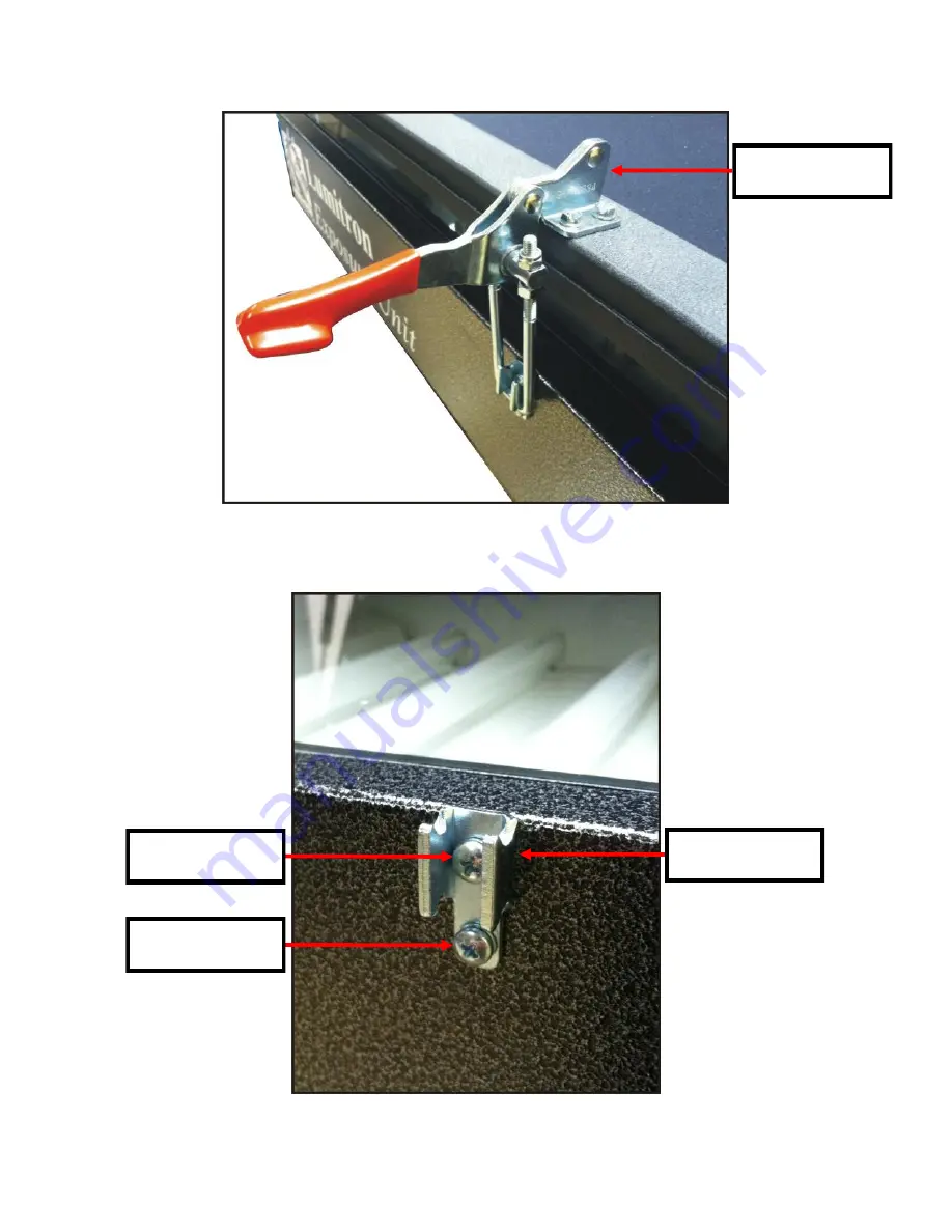
Lid Clamp
Clamp Hook
Hardware Included With Clamp
Part
D
Page 1: ...Lumitron Luminator REV 000...
Page 2: ...troduction 3 Standard Operating Guide 3 Features Specs 3 External Layout 4 8 Internal Layout 9 10 Wiring Diagrams 11 F A Q 12 14 Ballast to Lamp Relationship 15 Timer Setting and Programming 16 Compre...
Page 3: ...ace one end of the rope next to the vacuum nipple located toward the rear and in the center of the vacuum frame drape the other end of the rope across the inside squeegee side of the frame This will a...
Page 4: ...4 Front View Control Panel Main Power Switch Part A Timer 115V Part B Timer 220V EURO Only Part C...
Page 5: ...5 Lid Clamp Clamp Hook Hardware Included With Clamp Lid Clamp Part D Hardware Included With Clamp Hardware Included With Clamp...
Page 6: ...6 Gas Spring Ball Stud Gas Spring Part E Ball Stud Part F...
Page 7: ...ounted Hinge Part I Pan Head Screw Part H Lock Washer Part G Pan Head Screw Part W Modified Stem Part N Fender Washer Part O Vacuum Hose 2ft Part M Blanket Part J Vacuum Pump 115V Part L Vacuum Pump 2...
Page 8: ...8 Rear Mounted Receptacle Receptacle 115V 15A Part P Receptacle 250V 15A EURO Only Part Q...
Page 9: ...A Black Light Part R Lamp Socket Part S Black Light Part R Timer 115V Part B Timer 220V EURO Only Part C WARNING RISK OF ELECTRICAL SHOCK Turn ALL power to unit OFF before service All service should b...
Page 10: ...t 115V Part T Ballast 115V Part T Ballast 220V EURO Only Part U Ballast 220V EURO Only Part U Ballast 220V EURO Only Part U Ballast 115V Part T Ballast 115V Part T Ballast 115V Part T Ballast 220V EUR...
Page 11: ...11...
Page 12: ...ten the nylon lock nuts an equal amount of turns on each one and try closing the frame If it takes an excessive amount of force to lock them down back the nuts off and try again They should be firm bu...
Page 13: ...5 or 6 the right cover will need to be removed Image 3 and 4 Image 3 Left Ballast Bank Lamps 1 3 Image 4 Right Ballast Bank Lamps 4 6 With the correct cover now removed using the guide one page 15 to...
Page 14: ...the lights come on the timer will need to be replaced Image 6 5 The vacuum pump is not running With power to the unit off unplug the vacuum from the rear of the unit Next plug the unit into a recepta...
Page 15: ...t 1 Ballast 2 Ballast 3 Note The colors in this representation do not reflect the wire colors or harnesses in any way simply to differentiate the ballast to lamp relationship Lamp 5 Lamp 4 Lamp 3 Lamp...
Page 16: ...you want to resume the session you just need to press the start button again Counting will proceed from the point where stopped During this operation the run LED blinks once a second Once the timer ha...
Page 17: ...0 30 H Pan Head Screw 41 PHMS 250 60 I Hinge 47 75011 J Blanket 20502R K Vacuum Pump 220V EURO Only 31 76056 L Vacuum Pump 115V 31 76051 M Vacuum Hose 2 Feet 52 74014 N Modified Stem 75009 O Fender Wa...