


Operation and Use
Please follow the following instructions!
• Check the adjusting tools and keep these away from the grinding machine.
• Adjust and tighten all adjustable parts (such as the spark guard glass, workpiece
support, etc.) according to this operating manual.
• Before using, carry out a ring test of the grinding wheels and a test run without a
load.
• When grinding, do not apply excessive force, in order to avoid overloading the machine.
The workpiece can heat up intensely in the course of grinding. Cool the workpiece
down from time to time; otherwise there is a danger of burns. This grinding machine
is designed for short-time use. Switch the machine off after 30 minutes at the latest.
Before you continue with the work, wait until the machine has cooled down to room
temperature.
• In all cases, avoid hard impacts with the tool on the rotating grinding wheel.
Replacement of Wearing Parts
Should it become necessary to replace parts in the grinding machine, first pull the power
plug out of the electrical socket.
Replaceable Individual Parts
• Grinding wheels
• Workpiece support
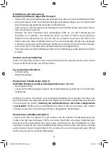
Changing the grinding wheel (fig. 4)
ATTENTION! Minimum permitted grinding wheel diameter is 110 mm
• Pull the mains plug
• Loosen the fastening screws on the protective cover and remove the protective cover.
Remove the 3 screws on the side of the protective hood and remove this. Through hol-
ding on to the opposite nut of the grinding wheel holder, you can loosen the nut (A)
(Attention, the grinding wheel is screwed in with a left-handed thread!). Next, take
off the flange (B). You can exchange the grinding wheel. The assembly takes place in the
opposite sequence.
Changing the sanding belt (fig.5)
Loosen the three screws (C) and remove the protective cover on the side. Loosen the
clamping bolt (9) for the upper belt idler by a few turns. Push the release lever (10) down
and pull the sanding belt off the rollers. Place the new sanding belt (4) across the middle
of the lower and upper roller and let go of the release lever (10). Now tighten the
clamping bolt (9) and mount the cover on the side.
22
1196979 BDA WB 240 SBS.indd 22
14.02.13 17:30
Summary of Contents for WB 240 SBS
Page 43: ...1 a b c 2 a b c d 42 1196979 BDA WB 240 SBS indd 42 14 02 13 17 30...
Page 44: ...e f 3 a b c d e f g h i j k 43 1196979 BDA WB 240 SBS indd 43 14 02 13 17 30...
Page 45: ...4 a b c d e f g h 5 a b 44 1196979 BDA WB 240 SBS indd 44 14 02 13 17 30...
Page 46: ...1 2 3 4 5 5 6 7 45 1196979 BDA WB 240 SBS indd 45 14 02 13 17 30...
Page 48: ...2 1 3 2 2 3 0 1 2 3 5 47 1196979 BDA WB 240 SBS indd 47 14 02 13 17 30...
Page 49: ...30 4 110 3 A 5 9 10 4 10 9 48 1196979 BDA WB 240 SBS indd 48 14 02 13 17 30...
Page 50: ...1 2 3 4 5 1 5 230 50 Hz 49 1196979 BDA WB 240 SBS indd 49 14 02 13 17 30...
Page 51: ...A B C 50 1196979 BDA WB 240 SBS indd 50 14 02 13 17 30...
Page 95: ...l 1 a b c 2 a b c d 94 1196979 BDA WB 240 SBS indd 94 14 02 13 17 30...
Page 96: ...e f 3 a b c d e f g h i j k 95 1196979 BDA WB 240 SBS indd 95 14 02 13 17 30...
Page 97: ...4 a b c d e f g h 5 a b X 96 1196979 BDA WB 240 SBS indd 96 14 02 13 17 30...
Page 98: ...1 2 3 4 5 5 6 7 97 1196979 BDA WB 240 SBS indd 97 14 02 13 17 30...
Page 100: ...2 mm 1 3 2 mm 2 3 0 1 2 3 5 99 1196979 BDA WB 240 SBS indd 99 14 02 13 17 30...
Page 101: ...30 4 110 mm 3 5 3 9 10 4 10 9 100 1196979 BDA WB 240 SBS indd 100 14 02 13 17 30...
Page 102: ...1 2 3 4 5 4 1 5 mm 230 V 50 Hz 101 1196979 BDA WB 240 SBS indd 101 14 02 13 17 30...
Page 103: ...A 102 1196979 BDA WB 240 SBS indd 102 14 02 13 17 30...