PRE-INSTALLATION
6 720 815 725 (2015/05)
11
▶ Drain and thoroughly flush the system to remove the flushing agent
and debris.
▶ It may be necessary to use a power flushing machine to aid the
cleansing procedure in some circumstances.
▶ Close the drain cocks and refill with fresh water and a suitable
inhibitor.
▶ Vent any air from the boiler and system.
INHIBITOR
Add a suitable inhibitor or combined inhibitor/anti-freeze, if the system
is exposed to freezing conditions, to the heating system in accordance
with the DWTA code of practice and manufacturer‘s guidelines.
WATER TREATMENT PRODUCTS
Suitable water treatment products can be obtain from the following
manufacturers:
ARTIFICIALLY SOFTENED WATER
It is possible to have an ion exchange water softener fitted to the cold
water system of the property. However, the boiler requires an untreated
cold water connection taken from the mains supply, before the water
softener, to the primary water filling point of the heating system.
Alternatively there are water softening/treatment devices that do not
adjust or alter the pH levels of the water. With these devices it may not
be necessary to provide an untreated water by-pass to the primary water
filling point of the heat system.
3.2
MAINS SUPPLY
3.2.1
ELECTRICAL SUPPLY
• Supply: 230V - 50 Hz, 140 Watts
• Cable: PVC insulated 0.75 mm2 (24 x 0.2 mm) temperature rated to
90°C.
• External 3A fuse to BS1362.
• The appliance must be earthed.
• This appliance must not be connected to a three phase supply.
• IPX4D.
• Wiring must comply with the latest IET wiring regulations.
3.2.2
GAS SUPPLY
• Boilers using Natural Gas (NG) must be connected to a governed
meter.
• Liquid Petroleum Gas (LPG) must be connected to a regulator.
• Installation and connection of the gas supply to the boiler must be in
accordance with BS6891.
• Under no circumstance should the size of the gas supply pipe be less
than 22 mm.
• The meter or regulator and pipe work to the meter must be checked,
preferably by the gas supplier. This is to ensure that the equipment is
in good working order and can meet the gas flow and pressure
requirements, in addition to the demand from any other appliance
being served.
3.2.3
WATER SUPPLY
WATER MAINS PRESSURE:
• Minimum mains water pressure: 1.5 up to 2.5 bar for maximum
performance.
• Maximum mains fed water pressure 10 bar. If necessary fit a
pressure reducing valve.
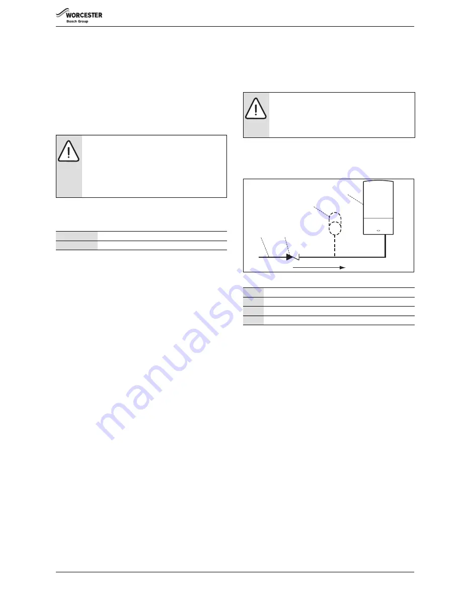
• Where the mains water supply has a non-return,
back flow prevention valve fitted, a mini expansion vessel (1) should
be connected to the mains water inlet pipe (2) between the non-
return valve (3) and the boiler (4) as shown below
Fig. 6
USE IN HARD WATER AREAS:
Normally there is no need for water treatment to prevent scale formation
as the maximum temperature of the HW heat exchanger is limited by the
electronic control.
In areas where temporary water hardness exceeds
200 ppm, consideration may need to be given to the fitting of a scale
prevention device. In such circumstances, the advice of the local water
authority should be sought.
WARNING:
Sealing agents
▶ Normally the addition of sealing agents to the system
water is not permitted as this can cause problems
with deposits left in the heat exchanger.
▶ In cases where all attempts to find a micro leak have
failed, Worcester, Bosch Group supports the use of
Fernox F4 leak sealer.
FERNOX
0870 601 5000 or www.fernox.com
SENTINEL
0800 389 4670 or www.sentinel-solutions.net
NOTICE:
Non-return, back flow prevention devices
(including those associated with water meters) fitted to
the mains water supply can cause a pressure build up
which could damage the boiler and other household
appliances.
1
Mini expansion vessel
2
Mains water inlet pipe
3
Non return valve
4
Boiler
1
4
3
2
6720643895-04.1Wo


