Pre-Installation
Worcester Commercial Boiler Series – 6720814332 (2019/04)
20
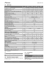
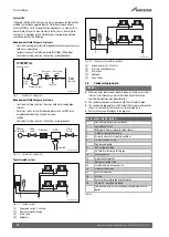
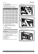
Table 11 Reduced flue lengths in metres
The total reduction length must never exceed the maximum flue length.
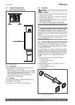
Weathering slates for 80/125 and 100/150
Flat roof, pitched roof.
3.8.4
Standard 100 mm flue systems
The standard concentric flue system provides for a max.
horizontalstraight length (
table 10, subsection 3.8.3). Full
instructions for fitting this flue are in subsection 3.8.5: ” Installation of
the horizontal flue” on page 20.
Important: Any horizontal flue system fitted to a condensing boiler must
be declined towards the appliance at an angle of 53mm per metre length
to prevent condensate dripping from the flue terminal. This means that
the clearance above the appliance must factor in the horizontal flue run
length. See fig. 21 on page 18.
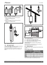
3.8.5
Installation of the horizontal flue
The standard flue is suitable for lengths up to 660mm (
For longer flue runs up to 20.0m for the 100/150 flue system and 7.7m
for the 80/125 flue system, flue extensions are available.
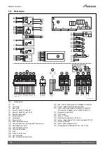
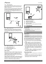
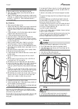
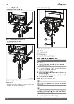
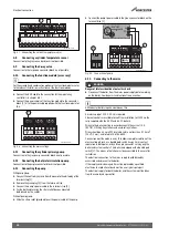
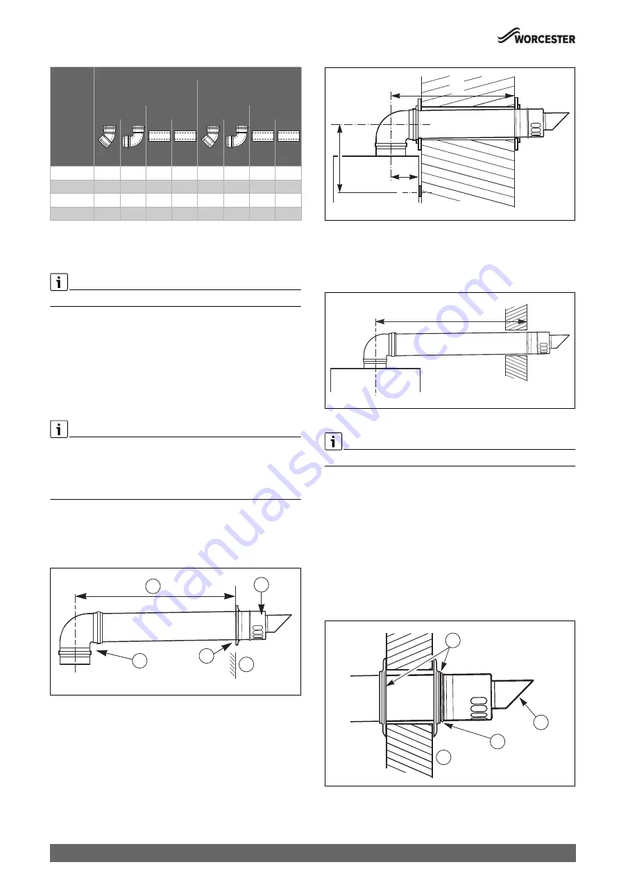
Fig. 27 Installation with horizontal flue kit
[1]
maximum length
[2]
terminal assembly
[3]
90° flue turret
[4]
finishing kit
[5]
outer wall
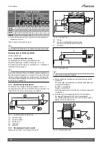
3.8.6
Flue pipe preparation and assembly
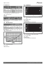
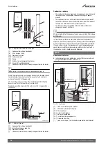
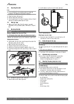
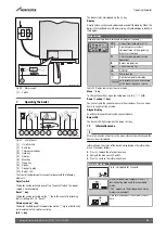
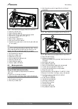
Measure the flue length L. Refer to figures 28 and 29.
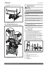
Fig. 28 Flue length - rear
[A]
152mm
[B]
337.5mm for Ø 80/125mm horizontal flue
339.5mm for Ø 100/150mm horizontal flue
[L]
flue length
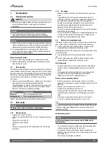
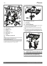
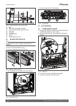
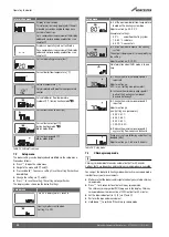
Fig. 29 Flue length - side
The flue must be inclined from the boiler.
▶ For connection into the elbow, a minimum length of pipe must be
maintained.
The flue gas pipe (inner pipe) and air intake pipe (outer pipe) must
maintain different lengths:
Air intake = L minus 50mm
Flue gas = L minus 70mm
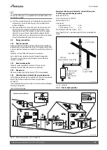
Mark off the lengths and cut to length. The cuts must be square and
free from burrs.
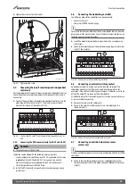
▶ Assemble flue system completely. Push the flue fully together.
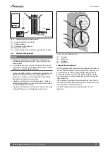
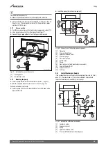
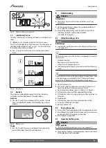
The slope of the terminal outlet [2] must face downwards.
The assembly will be made easier if a solvent free grease is lightly
applied to the male end of the flue.
Fig. 30 Flue terminal position
Model
Reduced flue length [m]
1)
1) For every bend or extension the max. flue length (L) has to be reduced by the
corresponding length in m.
concentric flue system
100/150mm
concentric flue system
80/125mm
bend
extension
bend
extension
45°
90°
0.5m
1m
45°
90°
0.5m
1m
50-V2
1.2
2.1
0.5
1.0
0.9
1.9
0.5
1.0
65-V2
1.2
2.1
0.5
1.0
0.9
1.9
0.5
1.0
85-V2
1.2
2.1
0.5
1.0
-
-
-
-
100-V2
1.2
2.1
0.5
1.0
-
-
-
-
0010025999-001
5
4
3
2
1
0010026000-001
A
L
B
0010026001-001
L
0010026002-001
4
3
2
1


