NOTE: READ THIS SECTION FULLY BEFORE COMMENCING
INSTALLATION
11.2 GENERAL FITTING.
Check that the appliance carton contains: Appliance, installers
instruction pack, pre-plumbing manifold, wall plate cross
member, user’s information pack and installer’s hardware pack.
Assemble the wall plate cross member to the pre-plumbing
manifold as shown in Fig. 14 using the two M4 thread forming
screws supplied in the hardware pack.
Check that the position chosen for the appliance is in accordance
with the instructions given in Sections 4 and 5.
Hold the wall plate to the wall. Check that the plate is horizontal.
See Fig. 14.
Leave the pre-fitted plastic cover in place to protect the valves
and ‘O’ rings from dust and dirt during installation.
Mark the position of the fixing holes and the position of the flue
hole centre line onto the wall. Draw a horizontal line along the
top of the wall plate cross member as shown in Fig. 14.
Rear Flue –
Mark a vertical line through the flue hole centre point.
Measure upwards 800mm from the horizontal line and mark the
point. This is the centre point of the flue duct hole. See Fig. 16.
Side Flue
– Extend the horizontal line from Fig. 14 along the
appropriate wall. Check that it remains horizontal and measure
800mm upwards and mark a horizontal line. Measure 197mm
from the junction of the walls and mark a vertical line which will
then give the position of the flue hole.
Drill the six fixing holes 60mm deep for No. 12 size plugs. Cut
the flue duct hole at 110mm diameter (150mm dia. for internal
fitting). Ensure that the hole is horizontal through the wall.
Fix the wall plate and check that it is horizontal before tightening
the six screws.
Connect the gas, water and pressure relief valve connections to
the manifold. The primary system should be flushed and treated
in accordance with the recommendations of BS 7593:1992.
Remove the plastic cover from the manifold, and make sure that
the “O” rings are fitted clean and lubricated.
Slide the appliance onto the pre-plumbing manifold ensuring
that the three pegs are located correctly. Secure with the two M6
nuts and washers at the top and screw the appliance to the
manifold at the bottom, using the three retaining caps and M6
bolts. See Fig. 15.
Access to these pegs and caps can be made easier by removing
the bottom panel.
Unscrew the automatic air vent cap. See Fig. 16.
If the air and flue duct assembly is to be fitted from inside the
room then the ducts must be cut to length, assembled and
inserted through the wall at this stage before fitting the flue
elbow to the appliance. Refer to Section 11.3 following for the
assembly of the air and flue ducts.
Remove the fan. See Section 14.3(e).
11.3 AIR AND FLUE DUCT PREPARATION AND ASSEMBLY
Check the contents of the standard flue duct kit against the
packing list. Similarly check the extension duct kits if applicable.
Remove all the packing from the ducts and terminal assembly.
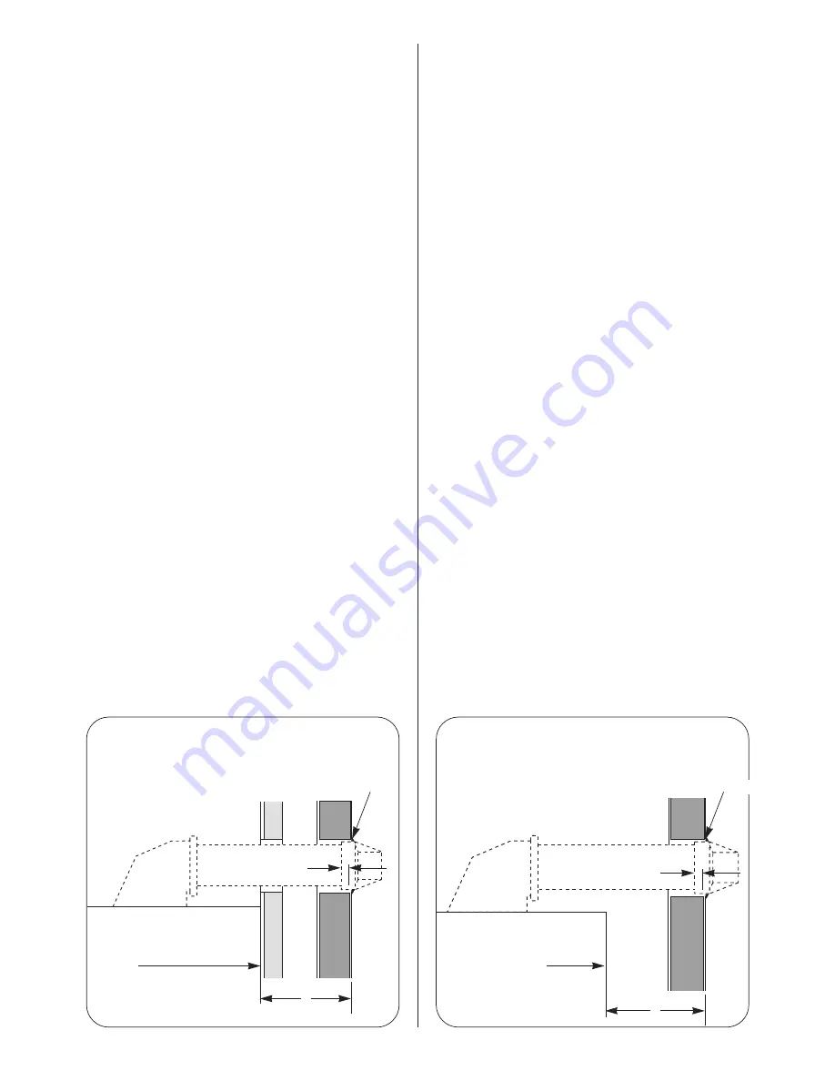
The standard flue kit accommodates a flue assembly up to
650mm long measured from the appliance casing to the outer
wall face. See dimension L, Figs.17 and 18. When dimension L is
greater than 650mm extension flue assemblies will be required.
Measure and cut the air and flue ducts to length ensuring that
the cuts are square and free from burrs. Always check the
dimensions before cutting the ducts.
Fit the restrictor ring in the flue terminal only when the overall
length of the flue is less than 1000mm and no additional flue
bends have been fitted.
11.4 EXTERNAL FITTING OF THE DUCT ASSEMBLY
Rear Flue Assembly
Measure distance L. See Fig. 17.
Air duct length = L + 146mm.
Flue duct length = L + 181mm.
Do not cut the drilled end of either duct.
Assemble the air and flue ducts to the terminal. Drill through the
holes in the terminal into the air duct and fix using the screws
provided. See Fig. 22. Join the extension ducts to the standard
ducts as indicated in Fig. 20, making sure the seal is in place.
Drill and screw together the air ducts.
From outside, push the assembly through the wall and enter the
ducts into the flue outlet turret.
Pull back the air duct slightly to allow access to the flue duct.
Drill through the flue duct and fix with the screws provided. Push
the air duct into the turret. Drill and fix the air duct to the turret.
See Fig. 19.
Align the flue turret with the 4 holes on the appliance and screw
down. See Fig. 16.
Make good the internal and external brickwork or rendering.
Refit the fan. Do not use any sealant on the joint. Replace the
inner casing cover.
Side Flue Assembly
Measure distance L. See Fig. 18.
Air duct length = L + 175mm.
Flue duct length = L + 210mm.
Do not cut the drilled end of either duct.
Assemble the air and flue ducts to the terminal. Drill through the
holes in the terminal into the air duct and fix using the screws
provided. See Fig. 22. Join the extension ducts to the standard
ducts as indicated in Fig. 20, making sure the seal is in place.
Drill and screw together the air ducts.
From outside, push the assembly through the wall and enter the
13
Fig. 17. Flue duct length (rear flue).
Fig. 18.
Flue duct length (side flue).
L
L
Make good
External
wall face
Rear face of appliance
and face of mounting
wall
10mm
Make good
External
wall face
Appliance side
panel
10mm


