background image

4

3.1. FLUE HEIGHT AND OFFSETS.

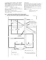
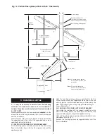
Determine  the  height  of  the  flue  system  and  if  offsets  are
needed  for  the  system  to  miss  ceiling/roof  joists  and  any
other obstruction. Refer to Fig. 8.

3.2. INSTALLATION OF BOILER.

Refer  to  the  relevant  Installation  and  Servicing  Instructions
for  the  fitting  of  the  wall-mounting  frame  assembly  and  the
boiler.
Flush the system and, where required, the cold water supply
before connecting the boiler.

3.3. FLUE KITS AND EXTENSIONS.

Remove  all  the  packing  from  the  ducts,  flue  terminal
assembly and flue bends.

Important:

The  air  duct,  flue  duct,  flue  bends  and  the

terminal  assembly  are  made  from  aluminium  and  must  be
handled appropriately.

3.4. FLUE ADAPTOR

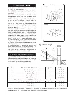
For some options a flue adaptor must be fitted into the spigot
on the top of the appliance casing. Refer to Fig. 9,10.
Fix  the  flue  adaptor  in  position  with  the  clamping  screw
ensuring that it is correctly located against the stop. Refer to
Fig. 5.
If  a  flue  bend 

(WH1  and  WR325  RSF  may  only  use  45°

bends)

is to be fitted directly to the top of the appliance then

the flue adaptor is not required.

3.5. FLUE SUPPORT

Flue  assembly  lengths  over  2000mm  should  be
appropriately supported. Refer to Fig. 6 and Section 5.4.

3.6. FIRE STOP SPACER

The fire stop spacer is supplied with the flue kit. Refer to Fig.
7 and Section 5.3.

3.7. ROOF FLASHING

The  roof  flashing  is  not  supplied.  This  is  available,  as  a
proprietary  item  (Selkirk  or  similar)  from  the  building
suppliers  to  suit  a  flue  size  of  125mm  diameter  and  to  suit
pitched and flat roofs.

3. Preparation and General Notes 

Fig. 5. Adaptor 

Appliance                                  front

Seal

Fixing screws

Vertical flue 
adaptor
88mm high.

Clamping 
ring

Ensure the ducts are 
correctly located into
the socketed joints.

Fix suitable support

bracket to existing joists

(screws not incuded)

twist ends bracket to suit

existing joists if

necessary

Roof space

Ceiling Fire stop spacer

Flue and air ducts

Existing joists

Fig. 6. Flue support - not supplied 

Fire stop spacer

Existing joists

25mm minimum gap to

combustible material

Drill a minimum of three holes 6mm
(0.25in.) dia. for No. 10 x 30mm
wood screws

Note: 

The small hole at each

corner of the plate is for temporary
fixing prior to marking off and
drilling

Reinforcement nogs

Fig. 7. Fire Stop Spacer 

Summary of Contents for 24Si II series

Page 1: ...6 L P G 28SiII GC NUMBER 47 311 67 N G GC NUMBER 47 311 68 L P G GB IE APPLIANCE OUTPUTS Domestic Central Heating Hot Water 24Si II 28Si II 24Si II 28Si II Minimum 6 9 kW 8 1 kW 6 9 kW 8 1 kW Maximum 24 kW 28 kW 24 kW 28 kW IMPORTANT THESE INSTRUCTIONS APPLY IN THE GB IE ONLY AND MUST BE LEFT WITH THE USER OR AT THE GAS METER It is IMPORTANT to read the instructions before starting work they have ...

Page 2: ... IS 813 Annex D1 must be completed by the installer and a copy supplied to the appliance operator for boilers installed in Eire Without the completion of the Log book and or declaration manufacturers may refuse to respond to a call out from a householder who will be advised that he or she must call back the installer who has not fulfilled his obligations to record the information required by the i...

Page 3: ...alves Thermostatically controlled or pressure equalising shower valves give extra comfort and protection If a pressure equalising valve is fitted then the domestic hot water temperature should be set to maximum 2 10 Safety The appliance must not be operated with the inner casing cover removed or without being full of water and pressurised The gas and electricity supplies must be turned off before ...

Page 4: ...XIMUM LENGTH mm 725 725 EXTENDED FLUE MAXIMUM LENGTH mm 4000 2500 FLUE ASSEMBLY DIAMETER mm 100 100 Table 2 FLOW RETURN DIFFERENTIAL NOTE Minimum uncut length NOMINAL BOILER RATINGS 10 Minutes After Lighting BOILER ADJUSTED FOR G20 Natural Gas OUTPUT INPUT Net GAS RATE kW kW m bar m3 h 8 1 9 2 0 7 0 97 28 30 7 13 1 3 25 BOILER ADJUSTED FOR G31 Propane 8 1 9 2 2 8 0 38 28 30 7 34 5 1 25 Table 1 28S...

Page 5: ...EDBUK NUMBER LPG 80 5 80 SEDBUK BAND D D 5 GAS SUPPLY SYSTEM BASED ON NG G20 TOTAL LENGTH OF GAS SUPPLY PIPE COPPER metres 3 6 9 12 GAS DISCHARGE RATE PRESSURE DROP mbar m3 h PIPE DIAMETER mm 8 7 5 8 4 6 3 9 22 18 0 12 0 9 4 8 0 28 Table 7 CLEARANCES mm INSTALLATION SERVICE UNVENTILATED COMPARTMENT ABOVE FLUEELBOW 30 30 150 IN FRONT OF APPLIANCE 600 600 240 BENEATH APPLIANCE 200 200 200 RIGHT AND ...

Page 6: ...casing dimensions and required clearances for installation servicing All dimensions in mm 30 150 10 10 6 B C D E 190 A B C D 20 A B C D E F View of underside of appliance showing connections Valves shown closed Fig 7 Pipework connections All dimensions in mm 24Si II 400 114 600 740 230 360 200 200 F All dimensions in mm 114 28Si II 440 Fig 5 Unventilated compartment clearances 230 200mm 150mm from...

Page 7: ...h extension kits for flues upto 4m for natural gas and 2 5m for LPG The terminal must not cause an obstruction or the combustion products a nuisance Under some conditions the terminal might steam and positions where this might be a nuisance should be avoided Refer to Fig 8 If the terminal is less than 2m above a surface to which people have access then a guard must be fitted The guard must be even...

Page 8: ... when the appliance is at maximum temperature then an additional expansion vessel must be fitted as near to the appliance as possible in the return pipe The pressure gauge shows the system pressure Fill and pressurise the system through a WRAS approved filling kit Refer to Fig 10 and 11 An optional kit is available Refer to Section 16 The system and the appliance must be fully vented Repeated vent...

Page 9: ...st be in accordance with the requirements of the local Water Company The water hardness can be determined by reference to the local Water Company An isolating valve should be fitted to allow servicing The appliance requires a maximum of 2 8 m3 h 24Si II 3 25m3 h 28Si II of natural gas G20 or 1 08 m3 h 24Si II 1 25m3 h 28Si II of propane G31 Refer to Table 7 A natural gas appliance must be connecte...

Page 10: ...green 2 green brown blue blue brown white red yellow ST2 ST15 ST1 Pump Gas valve 2 green white black Overheat cut off device DHW sensor Air Pressure Switch black black green Safety valve red green yellow 2 brown Safety valve Regulator valve Earth tabs small tab L high speed red medium tab L low speed white large tab N black ST5 Code Plug black red black blue black blue ...

Page 11: ...k Indicators Settings Regulator valve Spark electrodes Error indicator reset Red Main valve Flow sensor CH sensor DHW sensor Air pressure switch Flame sense Overheat cut off 24V programmer if applicable Gas valve mode switch CH Control knob DHW control knob Convert AC to low voltage electronics Electronics microprocessor Safety Low Voltage Flame detect indicator Red ST2 centre pole Ls for other fe...

Page 12: ...and flue opening before drilling the fixing holes 60mm deep for the No 12 size plugs and cutting the flue duct hole at 110mm diameter 150mm diameter for internally fitted flues 11 5 Wall Mounting and Manifold Assembly Fit the plugs and insert the bottom screws Check that all service valves are closed Offer the assembly to the wall utilising the keyhole slots on the manifold assembly and fix to the...

Page 13: ... it away from any electrics or where it might be a hazard Lower the facia to gain access The pipe must not be less than 15mm in diameter and must run continuously downward outside the appliance Refer to Fig 20 13 65 65 65 65 Wall Frame Wall Frame CH Flow DHW Flow Gas DHW Cold Inlet CH Return Fibre Washer Fig 17 Manifold assembly All dimensions in mm Fig 20 Relief valve drain connection 1 Fig 18 Fa...

Page 14: ...rd flue can be telescopically adjusted to any length between 425mm and 725mm measured from the centre of the turret without the need to cut the ducts Fix the flue assembly together using the self tapping screws provided Refer to Fig 23 It will only be necessary to cut the standard assembly if L is less than 425mm Cut the flue turret assembly and the terminal assembly by the same amount eg if L 350...

Page 15: ... the cut ducts fit into the terminal assembly 11 10 Fitting the Flue Assembly with Access to the Terminal Prepare the flue duct assembly as described in Section 11 8 Apply the plastic tape to the air duct to be in contact with the external brickwork From inside push the assembly through the wall Align the flue turret and push fully onto the spigot on the appliance Tighten the clamping ring Refer t...

Page 16: ...propriate length eg X 406mm cut 100mm from the air duct and 120mm to cover the entry into the 45 or 90 elbow from the flue duct Refer to Fig 30 NOTE The flue system ducts between the elbows dimension Y requires the socketed ends of the first extension if two or more are used to be removed and the air and flue tubes to be cut to the same length Cut the ducts to a length Y 162mm Refer to Fig 29 The ...

Page 17: ...d have been tightened Undo the two screws and remove the connections cover panel Refer to Fig 32 Connect the mains supply lead to the appliance and secure in the cable clamp Make sure that the lead is isolated before connection Refer to Section 10 Check that there is sufficient loose lead to allow the release of the facia panel assembly and that the earth lead of the mains supply is longer than th...

Page 18: ...s connector cover fixing screws 2 3 Facia control panel 4 Earth connection tags 5 Earth connection screws 6 Cable clamp 7 Fuse F1 2A slow 8 Cable clamp 9 ST15 Pump 10 ST1 Fan 11 Fuse F2 1 25A slow 12 Code plug 13 Commissioning switch gas valve mode switch 14 Internal controls connectors 15 Mains and external controls connectors 230 Volt ST2 Remove Link 230 V Room Thermostat Connections Ns Ls LR ST...

Page 19: ...ance central heating return connection and pressurised to the same figure as the integral vessel 12 2 Set the Expansion Vessel Pressure The charge pressure of the expansion vessel as dispatched is 0 5bar which is equivalent to a static head of 5m The charge pressure must not be less than the static head at the point of connection A Schraeder type valve is fitted to the expansion vessel to allow th...

Page 20: ...r is set to operate continuously Set the room thermostat and the central heating temperature control to maximum The burner will light and the appliance will modulate its output from minimum to maximum over a period of about two minutes Check that all the radiators are heating up evenly Shut down all but one of the radiators and observe the burner pressure fall Open all the radiators and check that...

Page 21: ...he cap from the sample point on the top of the appliance Refer to Fig 37 Connect an approved sampling meter With the appliance at maximum rate and stable in the DHW mode expect readings of 24kW NG CO2 5 3 6 2 CO 0 002 0 010 LPG CO2 6 4 7 4 CO 0 004 0 010 28kW NG CO2 5 6 6 4 CO 0 006 0 010 LPG CO2 6 3 7 3 CO 0 003 0 010 NB For flues greater than 725mm without a restrictor the CO2 may be up to 0 5 l...

Page 22: ...sembly 5 Spark electrode assembly 6 Inner case cover fixing bottom 7 Burner assembly 8 Combustion chamber fixing screw 3 1 4 5 8 2 6 7 9 10 11 9 Inner case 10 Fan assembly 11 Inner case cover fixing top 12 Air pressure switch 13 Combustion sensing point 14 Fan harness 15 Main wiring harness 12 15 13 14 ...

Page 23: ...and injectors are clear Clean the electrodes replace if there is any sign of deterioration Clean the heat exchanger Cover the gas inlet tube and remove any deposits from the heat exchanger from the top and bottom Carefully straighten any distorted fins on the heat exchanger Check the combustion chamber insulation and replace if there is any sign of damage or deterioration Refer to Section 15 5 Cle...

Page 24: ...ets O rings sealant heat transfer paste where necessary Always check that any electrical connections are correctly made and that all screws are tight Remove casing and cover panels and lower the facia onto lower lugs as necessary to gain access to the components Refer to Section 14 Inspection and Servicing 15 1 Gas Valve Unscrew the union connections above and below the gas valve and remove the as...

Page 25: ...inner casing cover and the combustion chamber Remove the spark electrode connections Unscrew the two burner bracket fixing screws Release the union connection beneath the burner and remove the burner from the appliance Refer to Fig 46 and 51 Do not omit the gasket when fitting the new burner 25 Fig 50 Flame sense electrode 1 3 2 1 Flame sense electrode 2 Fixing screw 3 Burner blade assembly RH Fig...

Page 26: ...cabinet and lower the facia onto the lower support lugs Check that the appliance has been fully drained Unclip and pull out the valve body Refer to Fig 54 15 8 Flow Turbine Drain the DHW circuit as described at the start of Section 15 preceding Remove the clip on facia cover cabinet and lower the facia panel onto the lower support lugs Separate the in line connector Remove the two fixing clips and...

Page 27: ...a by gently pulling it away from the boiler to release the clips Remove the clock programmer assembly by releasing the clip at the top of the clock programmer and ease away from the control panel being careful not to pull on the connector lead Unplug the connector at the control board Refer to Fig 58 Comprehensive instructions are sent with the new control 15 13 Fan Remove the inner casing cover R...

Page 28: ...ctrical connections to the new pump head Take care not to scratch the mating surfaces 15 19 Expansion Vessel It will be necessary to remove the appliance from the wall to replace the expansion vessel Refer to Fig 37 Alternatively the specified replacement can be fitted into the heating system return as close to the appliance as possible Re fill and pressurise the system as described in Section 13 ...

Page 29: ...op of the appliance Refer to Fig 63 and 64 15 23 Sight Glass Remove and replace the inner casing cover complete Refer to Section 14 3 Inspection and Servicing Refer to Fig 42 29 Fig 62 Primary heat exchanger 1 2 3 4 5 6 1 Heat exchanger 2 CH flow return pipes 3 DHW inlet outlet pipes 4 Seal 5 Overheat thermostat 6 Primary sensor Fig 64 Air flow pressure switch 1 2 3 4 5 1 Electrical connections 2 ...

Page 30: ...77 Pump 1 8 716 143 116 0 21 E27 587 Expansion Vessel 1 8 715 407 154 0 22 H02 152 Control Board 1 8 748 300 488 0 23 E88 179 Fan Assembly 24Si II 1 8 716 104 814 0 24 E88 180 Fan Assembly 28Si II 1 8 716 104 815 0 25 E88 181 Flow Sensor 1 8 716 146 164 0 26 E88 182 Seal Door Extrusion 1 8 716 104 609 0 27 E88 183 Transformer 1 8 747 210 294 0 28 E88 184 Flow Regulator 24Si II 1 8 716 141 255 0 29...

Page 31: ...31 1 4 5 6 7 8 11 9 10 12 13 14 15 16 17 18 8 21 22 25 20 23 24 26 28 29 30 31 27 19 ...

Page 32: ...low temperature set by control knob 50 82 C DEMAND END Overrun function see overleaf CENTRAL HEATING FUNCTION AND AND DOMESTIC HOT WATER FUNCTION MAIN SWITCH ON Flow sensor signal Tap open DOMESTIC HOT WATER DEMAND Priority over CH demand Pump continue 4 seconds if primary temp above DHW setting Burner to MAX Modulate gas to maintain delivered water temperature set by control knob 40 60 C Is CH in...

Page 33: ...END CH DEMAND Pump runs for 3 minutes Pump on if primary temp above 80 until temp below 75 C AUTOFROSTAT FUNCTION Monitor central heating sensor Below 5 C 5 C to 9 C Above 9 C No demand and primary temperature below 8 C Internal Autofrostat demand Return to normal off state Fan low speed 35 seconds Fan low speed if primary temp above 80 C until below 75 C ...

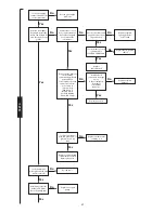
Page 34: ...o lights and no functions with demand No CH function DHW OK No DHW function CH OK Flash once per second Ignition lockout Overheat lockout Internal error Flash 4 times per second No mains Voltage supply Fuse F1 or F2 blown Transformer or connector failed Board fault No link at ST2 Ls to Lr or failed external control input to Lr Failed programmer Board fault Flow sensor failure DHW sensor LED 4 flas...

Page 35: ...nsformer from board Measure resistance across the two pairs of adjacent pins on the transformer Is any coil above 120 ohms Replace transformer Yes Yes No Replace control board No NOTE It is normal for there to be no facia lights if the boiler is in normal overtempera ture condition Continue this test if this fault occurs when the appliance is cold Is there a 230V AC live supply across Terminal ST2...

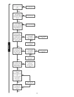
Page 36: ...the green and black wires terminals Is there continuity in the main harness Disconnect the 3 way in line connector to the turbine Is there 5VDC between the two outer pins main harness side Take care not to damage the pins No No Yes Yes Replace control board Replace main harness TEST C Yes Replace turbine No ...

Page 37: ...g below 100 ohms Replace gas valve Are the electrodes and gap and connections in good order Replace control board Remove both connectors from gas valve Is there continuity from these to multiway connector Repair or replace harness Repair or replace spark electrode or HT leads Is the gas supply connected and at the correct pressure Rectify gas supply problem No No No No No No Yes Yes Yes Yes Yes Ye...

Page 38: ...e efficiency of the gas water heat exchanger If there is still a problem investigate flue problems or replace burner or injector or heat exchanger Does the flashing fault signal occur at the start of a demand If flashing occurs at the end of a demand Gas valve leak is detected Replace gas valve No Yes If flashing occurs during a demand Pump could be partially blocked Clean pump flush system Re fix...

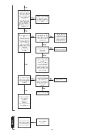
Page 39: ...sh fully home No No No No No Yes Yes Yes Check the DHW sensor Is it correctly fitted onto the pipe with heat conductive paste between the pipe and sensor Yes No Re fix sensor onto pipe Is the Code plug fitted and fully home Fit push fully home Yes No TEST E Check or replace CH sensor Test resistance across contacts 13 and 14 black blue wires Is it open circuit Turn off electrical supply Remove fan...

Page 40: ...fan or fan may not be running freely Inspect the flue Is it free of any restrictions Rectify flue problem Does the burner ignite burner light on and run for a short priod before the fault occurs Replace control board Repair cables or replace main harness Replace tubes If condensation has occurred also replace pressure switch and check condition of Venturi in the fan No No No No Yes Yes Yes Yes Tur...

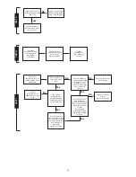
Page 41: ... heat exchanger blocked or gas valve sticking Hot water temperature always too hot during a demand not regulating TEST H Hot water sensor could be off or poorly fixed to pipe Repair or replace Yes Yes No Turbine sticking or seized Replace the turbine Increase potentiometer to allow more gas in CH mode No Check flow sensor with boiler cool slowly open a HW tap Does the boiler ignite with a flow of ...

Page 42: ...nd Service Instructions Section 12 5 for the setting of the gas valve and refer to Fig 1 Ensure that the joints on the gas valve to the burner and inlet are both checked for gas soundness 12 Refit the plastic sealing cap to the gas valve modulating valve and seal with a dab of paint or similar 13 Turn off the boiler and when cool peel off the arrow from the data plate on the combustion box front p...

Page 43: ...43 ...

Page 44: ...e subject to our official Conditions of Sale a copy of which may be obtained on application PUBLICATION 8 716 105 781a 07 03 Bosch Group Worcester Heat Systems Limited Bosch Group Cotswold Way Warndon Worcester WR4 9SW Telephone 01905 754624 Fax 01905 754619 Technical Helpline 08705 266241 www worcester bosch co uk This manual is to be used in conjunction with the variant part number of the bar co...

Page 45: ...41 311 54 55 28Si 47 311 51 52 WR325 52 311 02 C1 47 311 51 WH1 52 311 03 24CDi 47 311 30 31 24SiII 47 311 65 66 28CDi 47 311 34 35 28SiII 47 311 67 68 35CDiII 47 311 51 52 15SBi 41 311 43 45 24SBi 41 311 44 46 IMPORTANT THIS BOOKLET MUST BE READ FULLY IN CONJUNCTION WITH THE APPLIANCE INSTALLATION AND SERVICING INSTRUCTIONS THESE INSTRUCTIONS APPLY IN THE UK ONLY THESE INSTRUCTIONS ARE TO BE LEFT...

Page 46: ...able for installation in dwellings with pitched or flat roofs The minimum distance the Flue Terminal Assembly shall extend above the surface of the roof is 300mm This dimension is measured from the outside surface of a flat roof or the highest point on a pitched roof to the underside of the air inlet flange on the terminal assembly See Fig 2 Important All the Flue items referred to in this section...

Page 47: ...m straight length to not exceed 800mm or 1550mm for 2 x 45 bends When measuring between the centre lines of flue ducts an allowance must be made for the relevant elbow Refer to Fig 3 NOTE CBi WR 325 RSF 2 x 45 bends only 90 bends 0 5m 1 5m SBi CDi 80ic 0 5m C1 Si 75mm MODEL 15SBi 79mm NONE NONE 24SBi EQUIVALENT FLUE LENGTHS UP TO 1M EQUIVALENT FLUE LENGTHS 1M TO 4M EQUIVALENT FLUE LENGTHS UP TO 72...

Page 48: ... top of the appliance then the flue adaptor is not required 3 5 FLUE SUPPORT Flue assembly lengths over 2000mm should be appropriately supported Refer to Fig 6 and Section 5 4 3 6 FIRE STOP SPACER The fire stop spacer is supplied with the flue kit Refer to Fig 7 and Section 5 3 3 7 ROOF FLASHING The roof flashing is not supplied This is available as a proprietary item Selkirk or similar from the b...

Page 49: ... and pitched roofs Important The terminal assembly must extend at least 300mm above the surface or pitch of the roof The distance may vary depending upon the type of roof and surrounding structures In these instructions the distance is refered to as dimension F Refer to Fig 9 10 11 12 Fig 8 Marking out the flue assembly position Vertical Flue System no offset Appliance front Appliance front Vertic...

Page 50: ...han 300mm Duct Length H 92mm Derivation Dimension G 1100 Fmm Dimension H E G Refer to 2 2 for maximum duct length 4 Measurement of Ducts Air inlet flange Weather sealing collar Secure with screw provided and seal with silicone sealant Roof flashing not supplied Flat roof Pitched roof Flue terminal assembly 106mm diameter Fire stop spacer Air and flue duct extension kits 750mm Vertical flue adaptor...

Page 51: ...iameter marked on the inside surface of the roof Dimension K Refer to Fig 7 Note Dimension K for a pitched roof must go to the highest point of the hole diameter Determine dimension F Refer to Fig 1and 7 for the limiting figure Duct Length L 81mm Derivation Dimension G 1100 Fmm Dimension L K G Note The air duct must not be less than 100mm Air inlet flange Weather sealing collar Secure with screw p...

Page 52: ...ide surface of the roof Dimension K Refer to Fig 6 and 7 Note Dimension K For a pitched roof must go to the highest point of the hole diameter Determine dimension F which must not be less than 300mm Duct Length L 81mm Dimension G 1100 F mm Dimension L K G Air inlet flange Weather sealing collar Secure with screw provided and seal with silicone sealant Roof flashing not supplied Flat roof Pitched r...

Page 53: ...uts are square and free from burrs All dimensions refer to straight lengths and do not include the expanded ends Do not cut the expanded ends unless specifically instructed to do so 5 3 POSITION OF THE FIRE STOP SPACER ASSEMBLY Fit the fire stop spacer centrally over the hole in the ceiling Ensure the hole aligns with the flue spigot on top of the appliance casing 5 Installation of Flue Mark the f...

Page 54: ...at each stage of the system assembly that each section is properly aligned Each air and flue duct joint must be sealed and fixed Each air and flue duct connection to an elbow must be sealed with silicone sealant and fixed with the screws provided Support any sections of the system until they are permanetely fixed into place using suitable support brackets 5 5 ASSEMBLY OF DUCTS 5 5 1 AIR DUCTS Chec...

Page 55: ...s in the air duct Separate the assembly and apply silicone sealant to the outside of the air duct Re connect the assembly and fix with the screws provided Note The sealant and screws are not required for the flue duct Refer to Fig 13 5 10 SEAL THE TERMINAL ASSEMBLY TO THE ROOF From outside the building make good the roof structure and ensure the roof is weather sealed by fixing the roof flashing A...

Page 56: ...interests of continued improvement All goods sold are subject to our official Conditions of Sale a copy of which may be obtained on application PUBLICATION 8 716 145 030e 07 02 Bosch Group Worcester Heat Systems Limited Cotswold Way Warndon Worcester WR4 9SW Telephone 01905 754624 Fax 01905 754619 Technical Helpline 08705 266241 www worcester bosch co uk ...

Page 57: ...programmer to the facia and plug in the programmer connector into the four way connection on the board See Fig 1 Push the programmer into position ensuring that the lead is not trapped and that the clip has been properly engaged Replace white case Worcester Heat Systems Limited Cotswold Way Warndon Worcester WR4 9SW Telephone 01905 754624 Fax 01905 754619 Technical Helpline 0990 266241 Programmer ...

Page 58: ...h the appliance and or on the lighting instruction plate fitted to the appliance THESE INSTRUCTIONS APPLY IN THE UK ONLY THESE INSTRUCTIONS ARE TO BE LEFT WITH THE USER OR AT THE APPLIANCE CONFORMS TO THE ESSENTIAL REQUIREMENTS OF THE FOLLOWING DIRECTIVES 89 336 EEC Electromagnetic compatibility 73 23 EEC Low voltage Directive OFF TWICE ONCE ON ...

Page 59: ...nute period POWER UP CONDITION On power up when the battery back up has not been operational the pre set programme times will be in force ON1 OFF1 ON2 OFF2 MON FRI 6 30AM 8 30AM 4 30PM 10 30PM SAT SUN 7 00AM 9 00AM 4 00PM 11 00PM To return the programmer to the standard programme and 12 00am MON press the SET and buttons together BATTERY BACK UP Lifetime Lithium battery giving Display 1 Hour min 2...

Page 60: ...TO REPLACE THE PROGRAMMER Follow the preceding instructions 3 Programmer connection Fig 1 ST5 ...

Page 61: ...4 OFF TWICE ONCE ON ...

Page 62: ...he hours remember to take into account AM or PM press SET to lock in the hours Repeat the actions to set the minutes The display will show SET PROG TO SET THE PROGRAMME If you wish to change the programme press YES otherwise press SET twice to return to the run mode with the standard programme If you pressed YES then the display will ask SET MON FRI PROG If you want the weekday times to be the sam...

Page 63: ...ns for the central heating are OFF Off all the time TWICE On for two periods each day ONCE On for one period each day ON1 to OFF2 ON On all the time Operation of the SELECT button moves the arrow to the option required Mixing Once or Twice Options To have the Central Heating twice on some days and once on others programme the twice days as normal For the other days set ON1 and then OFF1 ON2 and OF...

Page 64: ...e Domestic Hot Water Temperature is controlled by the right hand knob on the facia Standard Programme To return to the standard programme press the SELECT and buttons together Refer to the User operating instruction leaflet or the lighting instruction plate on the appliance TO LIGHT AND STOP THE APPLIANCE 7 ...

Page 65: ...e interests of continued improvement All goods sold are subject to our official Conditions of Sale a copy of which may be obtained on application PUBLICATION 8 716 145 227b 02 02 Worcester Heat Systems Ltd Bosch Group Cotswold Way Warndon Worcester WR4 9SW Telephone 01905 754624 Fax 01905 754619 Technical Helpline 08705 266241 www worcester bosch co uk ...

Reviews: