


11
6
CLEARANCES
Your installer will
have provided adequate
space around the appliance
for safety and servicing. Do
not restrict this space by
the addition of cupboards,
shelves etc. close to the
appliance.
Minimum clearances in millimetres.
ROOM THERMOSTAT
A room thermostat may be fitted for control of the central heating
temperature. It will be located in one room of the home. The method
of setting a room thermostat varies with the type and manufacture.
Refer to the instructions supplied with the room thermostat.
THERMOSTATIC R
ADIATOR V
AL
VES
If thermostatic radiator valves are fitted to the system then they
must conform to the requirements of BS2767. The radiator located in
the room where the room thermostat is sited must be controlled by a
thermostatic radiator valve.
VENTILA
TION OF ROOM SEALED FANNED
FLUE (RSF) APPLIANCES
These are room sealed appliances and any ventilation openings
in a wall or door must not be obstructed. Do not allow the flue
terminal fitted on the outside wall to become obstructed or damaged.
NOTE:
Do not place anything on top of the appliance. If the
appliance is fitted in a compartment do not use the compartment for
storage purposes unless it conforms to the requirements of
BS 6798:1987: Section 6. It is essential that the airing space is
separated from the boiler space by a perforated non-combustible
partition as described in BS 6798:1987.
CIRCULA
TING PUMP
This may be fitted with a speed adjuster. If so it will be factory
set at maximum and should be adjusted by the installer to suit the
heating load.
10
INDICATOR LIGHTS
Green light:
MAINS : ‘ON’
TO LIGHT THE APPLIANCE
Check that the water valves to the central heating circuit are open.
Check that the grey needle on the pressure gauge is not below
the required pressure.
Switch on the mains electricity. Set the room thermostat, if
fitted, to maximum. Turn the central heating temperature control
knob to
‘MAX’.
The burner will light.. Set the central heating and hot
water temperature control knobs and the room thermostat/cylinder
thermostat, if fitted, to the desired temperature.
TO STOP THE APPLIANCE
For Short Periods
Turn the central heating temperature control knob fully anti-
clockwise to the
‘O’
position.
For Long Periods
Turn the CH temperature control knob
switch to the
‘O’
position. Switch off
the mains electricity.
A facia mounted mechanical
programmer will require resetting if
mains supply has been disconnected.
ELECTRICITY SUPPLY
FAILURE
If the electricity supply fails the
appliance will not operate. Once the
supply is restored the appliance will
return to normal operation. If a
programmer is fitted, check that the
settings have been maintained.
7
FROST PRECAUTIONS
If the appliance is not to be used for a long period of time and
there is a likelihood of freezing, then the appliance should be drained.
The Worcester Technical Helpline will advise you on suitable frost
precautions.
SERVICE
Annual servicing is important in order to ensure continuing high
efficiency and long life for your appliance. In the event of any
difficulty in making suitable servicing arrangements, Worcester
personnel or other competent persons will discuss regular servicing
arrangements and offer a comprehensive maintenance contract.
WARNING
If a gas leak exists, or is suspected, turn off the gas supply to the
appliance at the service cock and consult your local service engineer.
Do not touch any electrical switches to turn them either on or off.
Open all windows and doors. Do not smoke. Extinguish all naked lights.
CLEANING
Do not use abrasive cleaners on the outer casing. Use a damp
cloth and a little detergent.
APPLIANCE LOCKOUT
The appliance can be reset by pressing the reset button. Check
that the gas supply has not been interrupted.
If this condition continues to occur, then call a service engineer.
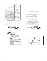
REMOV
AL AND REPLACEMENT
OF THE FRONT PANEL
(See Fig. 4)
Removal:
Holding the panel at the edges, slide it upwards to disengage the
clips and ease the top edge forwards and upwards to raise it clear of
the two pegs on the top edge of the facia.
Replacement:
Locate the two holes in the bottom edge of the front panel over
the two pegs on the top edge of the facia and reverse the removal
procedure.
Fig. 4. 15/24SBi with front panel removed.
Circulating
pump
Clip
Locating peg
Expansion
vessel
Gas valve
TO LIGHT AND STOP THE
APPLIANCE
15SBi
24SBi
Left-hand side
10
10
Right-hand side
10
10
In Front
600
600
Above
180
180
Below
200
200


