background image

 9 

Motor Wheel


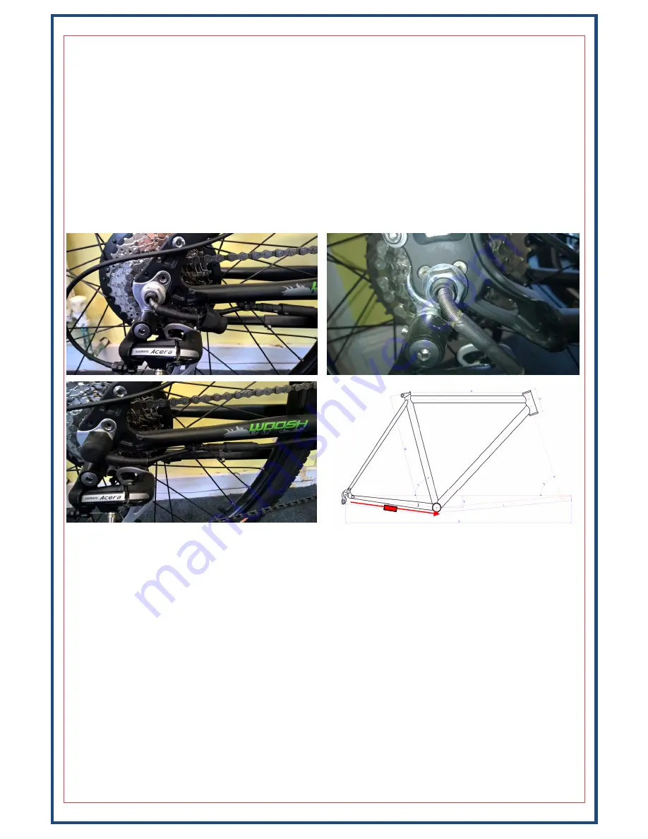
Remove the existing rear wheel and swap the tyre, tube and freewheel/cassette to the new motor wheel.  

You must ensure that the motor cable where it exits the spindle, points downwards towards the ground, 
see below for photos showing how the wheel should be fitted and the correct orientation of the cable. 

Once the wheel is properly installed, slide the rubber covers in place and secure the motor cable to the 
frame using cable–ties. The rubber cover for the side where the cable exits the spindle will need to be slid 
along the cable, and it should be fitted in such a way that the hole in the rubber cover keeps the motor 
cable pointing downwards as much as possible—see below. Also ensure that the metal coil/sheath is all 
the way down the cable so that it protects the cable from the somewhat sharp edges where the cable ex-
its the motor. 

The 

red 

arrow on the diagram above shows the typical route for the motor cable, with the quick-release 

connector (in the cable) indicated by the solid 

red 

box. 

FRONT Motor Wheel 


Remove the existing wheel and swap the tyre and tube to the new motor wheel. If you have purchased 
this kit and cannot carry out one or more of the procedures in this manual or do not have the necessary 
tools to complete the installation, you should seek the advice of a professional who can fit the kit for you. 

You must ensure that the motor cable where it exits the spindle, points downwards before looping back 
up, to form a drip –loop, this is to stop water running down the cable and collecting at the cable exit. 
Once the wheel is properly installed,  connect the motor cable and then secure the motor cable to the 
fork using cable–ties. 


Summary of Contents for Hub Kit

Page 1: ...Important For your own safety you must read this man ual before attempting to fit any part of the motor kit to your bike You must also ensure that you fit the kit in strict accordance with the instru...

Page 2: ...sor we would normally have determined which type is suitable for your bike before you finalised your order If we didn t please contact us before attempting to fit your kit Warranty Terms If your kit i...

Page 3: ...st disc and sensor speed sensor and magnet a thumb throttle brake levers and KingMeter J LCD Ensure that you have all of these items a photo of the items is show below so you can easily identify each...

Page 4: ...efit the bottom bracket With the bottom bracket re installed slide the PAS disc over the spindle so that it is as close as possible to the sensor without actually touching it You need to ensure that t...

Page 5: ...cannot slide the sensor down far enough if this is the case you can either swap the bottom bracket for a different model we can advise you on a suitable unit or contact us to see if a right side PAS i...

Page 6: ...6 Left side pedelec sensor cont Slide the larger rubber washer over the spindle and then re fit the crank...

Page 7: ...of your smallest chain ring in the case of double or triple rings The sensor itself is then attached to the base of the seat tube Pedelec disc With the sensor in place as per the photo above it now ne...

Page 8: ...o use the supplied washers if you bolt the cradle to the frame without using the washers the plastic will deform and eventually break Once the cradle has been secured to the frame fit the battery in p...

Page 9: ...all the way down the cable so that it protects the cable from the somewhat sharp edges where the cable ex its the motor The red arrow on the diagram above shows the typical route for the motor cable w...

Page 10: ...rake lever etc then slide the thumb throttle on and then secure it and the other components in position Depending on the configuration of the bike it may be more practical to mount the throttle and di...

Page 11: ...below Ensure that the arrows line up on both sides before pushing the connectors firmly together be careful with them and don t force them or you may bend damage the pins Also be sure to mate the cab...

Page 12: ...frame with cable ties it may be necessary to fit a spacer between the sensor and the frame to bring the sensor closer to the magnet otherwise it may not detect the magnet as it passes Position the ma...

Page 13: ...pedelec sensor and the modular cable The modular cable runs up to the handlebars and connects to the display unit the thumb throttle and the brake levers All of the connectors have ar rows on them tha...

Page 14: ...eed To switch between these modes press and hold the Up and Mode buttons for approx 1 second to cycle through the modes Walking Mode Start Aid The bike also supports a walking mode which is basically...

Page 15: ...pen the outer casing of the battery Do not attempt to repair the battery Do not immerse the battery in water Keep the battery away from children Do not drop pierce or otherwise damage the battery Ensu...

Page 16: ...tical the button on this one is a multi function button The button is used to turn the battery on and off as well as to indicate the status of the battery With the battery off pressing the button will...

Page 17: ...illustrating the problem and we ll normally get back to you within an hour or two on weekdays Support staff are not available at the weekends though if you send an email it will normally be read and r...

Reviews: