Manual 82510
Magnetic Pickups and Proximity Switches
Woodward
5
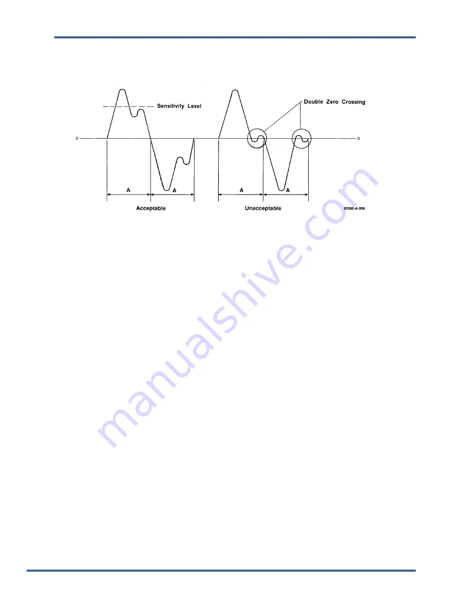
As the magnetic pickup-gear relationship begins to deviate from the specifications listed above, the MPU
output waveform may deteriorate to an unacceptable shape. Because the speed sensor detects zero-
crossings, the waveform should cross zero only twice for each tooth (once going positive and once going
negative, see Figure 1-2).
Figure 1-2. Magnetic Pickup Output Waveforms
MPU Installation
The magnetic pickup is available in short or long standard models, a standard metric model, hazardous
duty models, and explosion-proof models, including CSA/ATEX approved models (see Figure 1-3 for
dimensions and part numbers).
Mount the magnetic pickup radially to the outside diameter of the desired gear, either through a housing
or on a rigid bracket. Make sure the gear is of magnetic material. The gap between the pickup and the
outside diameter of the gear should be set normally between 0.25 mm and 1.02 mm (0.010 inch and
0.040 inch) at the closest point. Ensure the gear has less than 0.51 mm (0.020 inch) diametric runout.
Since the signal strength is inversely proportional to gap distance, a weak signal may be generated with
more than 1.02 mm (0.040 inch) gap. A shield of non-magnetic material may be installed between the
gear and the pickup if necessary for physical shielding. Since this material spaces the pickup face farther
from the gear, and since an electromagnetic force may be generated by eddy currents in the shielding
material, make sure the signal level is still high enough to operate the speed signal circuit.
Most electronic controls require a minimum output of 1.5 V (ac, rms) from the magnetic speed pickup at
the lowest controlling speed. Figures 1-4 and 1-5 show the maximum air gap allowed for each surface
speed and diametral pitch or gear module to produce this minimum required voltage.
Released


