background image

-27-

W1758 Owner's Manual (Mfg. Since 4/10)

M

A

INTE
N

A

N

CE

MAINTENANCE

Lubrication

Since all bearings for the Model W1758 are 

sealed and permanently lubricated, simply 

leave them alone until they need to be 

replaced. Do not lubricate them.

Wipe a lightly oiled shop rag on the outside 

of the headstock spindle. DO NOT allow any 

oil to get on the inside mating surface of 

the spindle.

Use the quill handwheel to extend the 

tailstock quill all the way out, and apply 

a thin coat of white lithium grease to the 

outside of the quill. DO NOT allow any 

lubricant to get on the inside mating sur-

face of the quill.

Cleaning the Model W1758 is relatively easy. Vacuum 

excess wood chips and sawdust, and wipe off the remain-

ing dust with a dry cloth. If any resin has built up, use a 

resin dissolving cleaner to remove it.

Remove any debris or oily substances from the inside of 

the spindle and quill.

Cleaning

Regular periodic maintenance on your machine will 

ensure its optimum performance. Make a habit of 

inspecting your machine each time you use it. 

Check for the following conditions and repair or 

replace when necessary:

  Loose mounting bolts.

  Worn switch.

  Worn or damaged cords and plugs.

  Damaged V-belt.

  Any other condition that could hamper the safe 

operation of this machine.

General

MAKE  SURE  that  your  machine  is 

unplugged during all maintenance pro-

cedures! If this warning is ignored, seri-

ous personal injury may occur.

Lathe Bed

Protect the unpainted cast iron lathe bed by wiping it 

clean after every use—this ensures moisture from wood 

dust does not remain on the bare metal surfaces. Keep 

your lathe bed rust-free with regular applications of qual-

ity lubricants.

Tailstock

To disassemble the tailstock for cleaning, loosen the set 

screw above the handwheel, then completely unthread 

the handwheel from the threads of the quill. Except for 

the live center, thoroughly clean all of the unpainted 

parts with mineral spirits and apply a thin coat of light 

machine oil to these surfaces.

When re-assembling the tailstock, thread the handwheel 

back onto the quill, tighten down the set screw that 

secures it, then back the screw off one full turn so that 

the handwheel can freely rotate.

Summary of Contents for SHOP FOX W1758

Page 1: ...NTERNATIONAL INC REVISED MARCH 2013 TS WARNING NO PORTION OF THIS MANUAL MAY BE REPRODUCED IN ANY SHAPE OR FORM WITHOUT THE WRITTEN APPROVAL OF WOODSTOCK INTERNATIONAL INC FOR MODELS MANUFACTURED SINCE 4 10 Printed in China OWNER S MANUAL MODEL W1758 VARIABLE SPEED WOOD LATHE WITH DIGITAL READOUT 9397TS ...

Page 2: ...ng grinding tool integrity and the usage of personal protective equipment The manufacturer will not be held liable for injury or property damage from negligence improper training machine modifications or misuse Some dust created by power sanding sawing grinding drilling and other construction activities contains chemicals known to the State of California to cause cancer birth defects or other repr...

Page 3: ...loor 12 Assembly 12 Test Run 14 OPERATIONS 15 General 15 Adjusting Headstock 16 Adjusting Tailstock 17 Adjusting Tool Rest 17 Installing Removing Headstock Center 18 Installing Removing Tailstock Center 19 Installing Removing Faceplate 20 Selecting Turning Tools 21 Spindle Turning 22 Faceplate Turning 24 Outboard Turning 25 Sanding Finishing Using the Lathe 25 ACCESSORIES 26 Wood Lathe Accessories...

Page 4: ...p operation maintenance and service of this product We stand behind our machines In the event that questions arise about your machine please contact Woodstock International Technical Support at 360 734 3482 or send e mail to tech support shopfox biz Our knowledgeable staff will help you troubleshoot problems and process warranty claims INTRODUCTION If you need the latest edition of this manual you...

Page 5: ...5 x 17 in Must Ship Upright N A Carton 2 Type Cardboard Box Content Legs Weight 95 lbs Length x Width x Height 32 x 16 x 13 in Must Ship Upright N A Electrical Power Requirement 110V Single Phase 60 Hz Prewired Voltage 110V Full Load Current Rating 14A Minimum Circuit Size 20A Connection Type Cord Plug Power Cord Included Yes Power Cord Length 8 ft Power Cord Gauge 16 AWG Recommended Power Cord N ...

Page 6: ...ter Height 43 in Headstock Rotation 0 60 90 120 180 deg Spindle Information Spindle Taper MT 2 Spindle Thread Size 1 in Spindle TPI 8 TPI Spindle Thread Direction Right Hand Spindle Bore 3 8 in Type of Included Spindle Center Spur Tailstock Information Tailstock Taper MT 2 Type of Included Tailstock Center Live Construction Bed Precision Ground Cast Iron Frame Cast Iron Stand Cast Iron Base Cast I...

Page 7: ...ol Rest G Tool Rest Base with Extension H Tailstock Locking Lever I Live Center A H P Q R I J K M N O B C D E F G L J Quill Locking Lever K Quill Handwheel L Lathe Bed M Tool Rest Extension Locking Lever N Tool Rest Base Locking Lever O Tool Rest Locking Lever P Headstock Rotation Locking Pin Q ON OFF Switch with Lockout Key R Headstock Locking Lever ...

Page 8: ...or alcohol when tired or when distracted ELECTRICAL EQUIPMENT INJURY RISKS You can be shocked burned or killed by touching live electrical components or improperly grounded machinery To reduce this risk only allow an electrician or qualified service personnel to do electrical installation or repair work and always disconnect power before accessing or exposing electrical equipment DISCONNECT POWER ...

Page 9: ...h moving parts or flying debris make sure they are properly installed undamaged and working correctly FORCING MACHINERY Do not force machine It will do the job safer and better at the rate for which it was designed NEVER STAND ON MACHINE Serious injury may occur if machine is tipped or if the cutting tool is unintentionally contacted STABLE MACHINE Unexpected movement during operation greatly incr...

Page 10: ...re range of motion EYE FACE PROTECTION Always wear a face shield and safety glasses when operating lathe PROPER APPAREL Do not wear gloves necktie or loose clothing Keep keep long hair away from rotating spindle SPEED RATES Select correct spindle speed for workpiece size type shape and condition Use low speeds when roughing or when turning large long or non concentric workpieces Allow spindle to r...

Page 11: ...round pin have it replaced by a qualified electrician If you are unsure about the wiring codes in your area or you plan to connect your machine to a shared cir cuit you may create a fire or circuit overload hazard consult a qualified electrician to reduce this risk Operating Voltage Amp Draw Min Circuit Size Plug Receptacle Extension Cord 110V Operation 14 Amps 20 Amps NEMA 5 15 14 Gauge Figure 1 ...

Page 12: ...on the machine or examine the pack aging materials carefully Occasionally we pre install cer tain components for safer shipping Box 1 Inventory Figures 2 3 Qty A Lathe Unit 1 B Faceplate 6 1 C Hardware Bag 1 D Knockout Tool 1 E Flat Wrenches 32mm 2 F Spur Center 1 G Live Center 1 H Tool Rest Handle 1 I Hex Wrenches 3 4 6mm 1 Ea J Cap Screws M8 1 25 x 35mm 8 K Quill locking lever 1 L Lock Washers 8...

Page 13: ... you are away NEVER allow untrained visitors in your shop when assem bling adjusting or operat ing equipment Cleaning Machine The table and other unpainted parts of your machine type are coated with a waxy grease that protects them from corrosion during ship ment Clean this grease off with a solvent clean er or citrus based degreaser DO NOT use chlo rine based solvents such as brake parts cleaner ...

Page 14: ...ounting to Shop Floor NOTICE Anchor studs are stronger and more permanent alter natives to lag shield anchors however they will stick out of the floor which may cause a tripping hazard if you decide to move your machine at a later point Figure 5 Typical fasteners for mounting to concrete floors Assembly Using Machine Feet Using machine feet shown in Figure 6 gives the advan tage of fast leveling a...

Page 15: ...uill keyway so that the quill can move in and out of the tailstock without rotating Figure 8 Securing lathe to legs Figure 9 Installing tool rest handle Figure 11 Digital readout installed onto the headstock viewed from the back To safely secure a center in the tailstock quill the quill locking lever must be aligned with the quill keyway and fully tightened Failure to follow this procedure could r...

Page 16: ...from the machine 3 Connect the machine to the power source 4 Turn the lathe ON by lifting up on the ON OFF switch and verify that it operates correctly When operating correctly the machine runs smoothly with little or no vibration or rubbing noises Investigate and correct strange or unusual noises or vibrations before operating the machine fur ther Always disconnect the machine from power when inv...

Page 17: ...ecom mend that you read books trade articles or seek training from an experienced wood lathe operator before perform ing any unfamiliar operations Above all your safety should come first Always wear an approved safety face shield and a respirator when operating this machine Failure to comply may result in serious personal injury DO NOT investigate problems or adjust the machine while it is running...

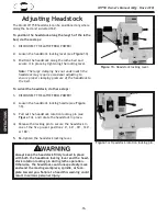
Page 18: ...To swivel the headstock do these steps 1 DISCONNECT THE LATHE FROM POWER 2 Loosen the headstock locking handle see Figure 13 3 Pull out the headstock rotation locking pin see Figure 14 and rotate the headstock in place 4 Release the locking pin to secure the headstock in one of the five pre set positions 0 60 90 120 or 180 5 Re tighten the headstock locking lever Figure 13 Headstock locking lever ...

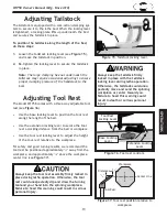
Page 19: ...ure to heed this warning could result in death or serious personal injury Adjusting Tool Rest The Model W1758 comes with a three way adjustable tool rest see Figure 16 Use the base locking lever to position the tool rest along the length of the bed Use the extension locking lever to secure the tool rest a working distance from the bed or workpiece Use the tool rest locking lever to adjust the heig...

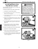
Page 20: ...center is securely installed by attempting to pull it out by hand a properly installed center will not pull by hand To remove the headstock spur center do these steps 1 DISCONNECT THE LATHE FROM POWER 2 Hold a clean rag under the spindle or wear a glove to catch the spur center when you remove it 3 Insert the knockout tool through the outboard end of the spindle and firmly tap the center catching ...

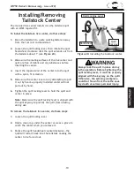
Page 21: ...out by hand a properly installed center will not pull out by hand 6 Tighten the quill locking lever to hold the quill and center in place Note Make sure the quill locking lever is aligned with the quill keyway to prevent the quill from rotating during use To remove the tailstock live center do these steps 1 Loosen the quill locking lever 2 Hold a clean rag under the center or wear a glove to catch...

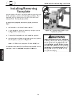
Page 22: ...ctions 3 Thread the faceplate onto the headstock spindle 4 Using the two included 34mm flat wrenches tighten the faceplate as shown in Figure 21 Note To remove the faceplate reverse Steps 3 4 For detailed instructions on mounting a workpiece to the faceplate refer to Faceplate Turning on Page 24 Figure 21 Tightening faceplate onto headstock spindle Always make sure that the workpiece is firmly att...

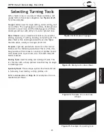
Page 23: ...uble ground with one side higher than the other usually at an angle of 20 40 Scrapers Typically used where access for other tools is limited such as hollowing operations This is a flat dou ble ground tool that comes in a variety of profiles round nose spear point square nose etc to match many dif ferent contours Parting Tools Used for sizing and cutting off work This is a flat tool with a sharp po...

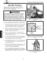
Page 24: ...point of both ends of your workpiece by drawing diagonal lines from corner to corner across the end of the workpiece see Figure 27 2 Using a wood mallet tap the point of the spur cen ter into the center of the workpiece on both ends leaving an indented center mark 3 Use a 1 4 drill bit to drill a 1 4 deep hole at the center mark on the workpiece end to be mounted on the headstock spur center 4 To ...

Page 25: ...rning Use the slower speeds for large workpieces of diameters of 4 and over and for rough cutting Use the middle range speeds for workpiece diam eters of 2 4 Use the faster speeds for workpieces under 2 and for finish turning Keep the turning tool on the tool rest the ENTIRE time that it is approaching the workpiece and it is in contact the workpiece Learn the correct techniques for each tool you ...

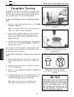
Page 26: ...k that is securely glued to the workpiece To mount your workpiece to a backing block do these steps 1 Make the backing block from a piece of scrap wood that is flat on both sides and is free of knots and splits 2 Locate and mark the center of both the workpiece and the backing block 3 Drill a 1 4 hole completely through the backing block at its center 4 Looking through the hole in the backing bloc...

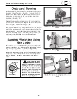
Page 27: ...est assembly will not work for your operation you must use a free standing tool rest not supplied Figure 33 Headstock positioned outboard at 90 Figure 34 Headstock positioned outboard at 180 Sanding Finishing Using the Lathe The lathe can be used for finishing procedures after the turning operations are complete such as sanding polish ing and applying finishes by hand see Figure 35 Note Whenever p...

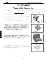
Page 28: ... insert The D1089 Steelex 4 Jaw Chuck for Wood Lathes is another must have for the serious wood turner This 4 jaw chuck is an indepen dent type chuck that is used for square and odd shaped pieces Each jaw tightens individually and can be turned around to hold larger dimension workpieces Threaded insert required for mounting such as the D1098 Steelex 1 x 8 TPI RH threaded insert Accessories The D23...

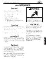
Page 29: ... of inspecting your machine each time you use it Check for the following conditions and repair or replace when necessary Loose mounting bolts Worn switch Worn or damaged cords and plugs Damaged V belt Any other condition that could hamper the safe operation of this machine General Make sure that your machine is unplugged during all maintenance pro cedures If this warning is ignored seri ous person...

Page 30: ...ign the headstock and tailstock centers do these steps 1 DISCONNECT THE LATHE FROM POWER 2 With the headstock and tailstock centers installed slide the tailstock up to the headstock 3 Loosen the headstock locking lever and swivel the headstock so that the tips of the centers touch as illustrated in Figure 36 then lock the headstock securely in place Figure 36 Center tips touching to ensure proper ...

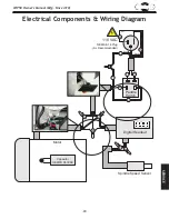
Page 31: ...ince 4 10 SERVICE Electrical Components Wiring Diagram Neutral Hot Ground 110 VAC NEMA 5 15 Plug As Recommended Paddle Switch Digital Readout Spindle Speed Sensor Motor Bk Bk Bk Bk Bk Wt Wt Wt Wt Gr Gr Gr Rd Capacitor 100MFD 250VAC ...

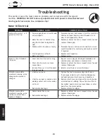
Page 32: ...1 Short circuit in line cord or plug 2 Short circuit in motor or loose connections 3 Incorrect fuses or circuit breakers in power supply 1 Inspect cord or plug for damaged insulation and shorted wires and replace extension cord 2 Replace or adjust fan cover inspect motor fan and replace if damaged 3 Install correct fuses or circuit breakers Vibration noise while machine is running noise changes wh...

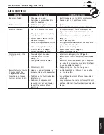
Page 33: ...d stable on the floor 5 Tighten motor mounting bolts 6 Replace V belt refer to Page 28 7 Replace spindle bearing s Chisels grab or dig into workpiece 1 Tool rest adjusted too low 2 Tool rest set too far from workpiece 3 Wrong chisel tool being used 4 Chisel tool is dull 1 Adjust tool rest higher refer to Page 23 2 Move tool rest closer to workpiece refer to Page 23 3 Use correct chisel tool educat...

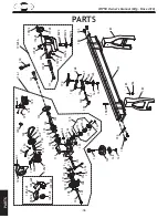
Page 34: ...115 2 115 4 116 116 1 117 118 119 120 121 122 123 124 125 126 127 128 129 129 1 130 131 132 133 134 135 136 137 138 139 140 141 142 143 144 145 146 147 148 149 150 151 152 153 154 157 158 159 160 161 162 163 164 165 166 167 168 169 170 171 172V2 173V2 174V2 175V2 176V2 177V2 178V2 180V2 181V2 182V2 183 184 185 186 187 108 200 201 183 184 187 173V2A PARTS ...

Page 35: ... REST CLAMP PLATE 116 X1758116 HEADSTOCK CASTING 165 X1758165 TOOL REST PIVOT BOLT 116 1 X1758116 1 HEADSTOCK ASSEMBLY 166 X1758166 LOCK HANDLE ASSY M10 1 5 X 15 117 XPK93M KEY 4 X 4 X 80 167 XPR08M EXT RETAINING RING 19MM 118 XPR06M EXT RETAINING RING 16MM 168 X1758166 LOCK HANDLE ASSY M10 1 5 X 15 119 X1758119 MOTOR SHAFT SLEEVE 169 X1758169 TOOL REST EXTENSION ARM 120 X1758120 COMPRESSION SPRIN...

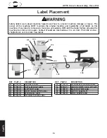
Page 36: ...in Contact Woodstock International Inc at 360 734 3482 or www shopfoxtools com to order new labels 191 194 190 192 199 196 198 195 193 197 189 REF PART DESCRIPTION REF PART DESCRIPTION 189 X1758189 MACHINE ID LABEL 195 X1758195 ENTANGLEMENT WARNING LABEL 190 X1758190 DIGITAL READOUT LABEL 196 XPPAINT 1 SHOP FOX WHITE TOUCH UP PAINT 191 X1758191 ELECTRICITY LABEL 197 X1758197 BLACK PIN STRIPE LABEL...

Page 37: ..._ No 5 Would you recommend Shop Fox products to a friend ______ Yes _____ No 6 What is your age group ______ 20 29 ______ 30 39 _____ 40 49 ______ 50 59 ______ 60 69 _____ 70 7 What is your annual household income ______ 20 000 29 000 ______ 30 000 39 000 _____ 40 000 49 000 ______ 50 000 59 000 ______ 60 000 69 000 _____ 70 000 8 Which of the following magazines do you subscribe to 9 Comments _ _...

Page 38: ...tape along edges please do not staple FOLD ALONG DOTTED LINE FOLD ALONG DOTTED LINE Woodstock international inc p o box 2309 bellingham wa 98227 2309 Place Stamp Here ...

Page 39: ... of Woodstock International Inc s warranty then the original owner must bear the cost of storing and returning the product This is Woodstock International Inc s sole written warranty and any and all warranties that may be implied by law including any merchantability or fitness for any particular purpose are hereby lim ited to the duration of this written warranty We do not warrant that Shop Fox ma...

Page 40: ...High Quality Machines and Tools Woodstock International Inc carries thousands of products designed to meet the needs of today s woodworkers and metalworkers Ask your dealer about these fine products ...

Reviews: