Woodstock SHOP FOX M1044 Owner'S Manual Download Page 21

-19-

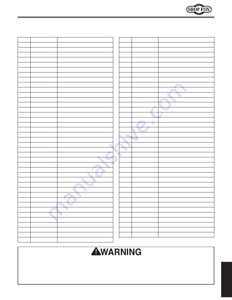
M1044 52" Foot Shear

PA

RT

S

Parts List

REF

PART

#

DESCRIPTION

REF

PART

#

DESCRIPTION

1

XM104401

BACK

GAUGE

ASSY

46

XM1044046

STRAIGHTENER

ROD

4

XM104404

FOOT

PEDAL

47

XPN02M

HEX

NUT

M10-1.5

5

XPSS10M

SET

SCREW

M10-1.5

X

20

48

XPSB72M

CAP

SCREW

M10-1.5

X

30

6

XM104406

BEVEL

GAUGE

49

XM1044049

GIB

7

XM104407

WING

NUT

50

XPSS15M

SET

SCREW

M12-1.75

X

12

8

XPW02

FLAT

WASHER

3/8"

51

XPW04M

FLAT

WASHER

10MM

9

XM104409

T-NUT

STUD

52

XPW04M

FLAT

WASHER

10MM

10

XM1044010

FRONT

STOP

53

XPSB90M

CAP

SCREW

M10-1.5

X

55

11

XPN02M

HEX

NUT

M10-1.5

54

XPB31M

HEX

BOLT

M10-1.5

x

40

12

XPB32M

HEX

BOLT

M10-1.5

X

25

55

XM1044055

FIXED

KNIFE

(LOWER)

13

XM1044013

EXT

BAR

SCREW

56

XM1044056

MOVING

KNIFE

(UPPER)

14

XM1044014

ROD

BRACKET

57

XPN05M

HEX

NUT

M16-1.5

15

XM1044015

STUD

58

XPW08M

FLAT

WASHER

16MM

16

XM1044016

LOCK

KNOB

59

XPB113M

HEX

BOLT

M16-2

X

120

17

XPN02M

HEX

NUT

M10-1.5

61

XPSB47M

CAP

SCREW

M10-1.5

X

40

18

XM1044018

ADJUSTABLE

SCREW

62

XPSS39M

SET

SCREW

M10-1.5

X

50

19

XM1044019

ADJUSTABLE

DIAL

63

XM1044063

TABLE

SCALE

WASHER

20

XM1044020

ADJUSTABLE

BLOCK

64

XM1044064

TABLE

SCALE

SCREW

21

XM1044021

RIGHT

BACK

GAUGE

EXT

BAR

65

XM1044065

RIGHT

TABLE

SCALE

22

XM1044022

LEFT

BACK

GAUGE

EXT

BAR

66

XM1044066

LEFT

TABLE

SCALE

23

XM1044023

BACK

GAUGE

STOP

67

XPSB58M

CAP

SCREW

M8-1.25

X

12

24

XM1044024

BACK

GAUGE

ROD

68

XM1044068

FINGER

GUARD

26

XM1044026

HINGE

PIN

69

XPW06M

FLAT

WASHER

12MM

28

XM1044028

BOTTOM

SWIVEL

SCREW

70

XPB125M

HEX

BOLT

M12-1.75

X

65

29

XM1044029

TOP

SWIVEL

SCREW

71

XPN09M

HEX

NUT

M12-1.75

30

XPW04M

FLAT

WASHER

10MM

72

XM1044072

PRESSURE

PLATE

SPRING

STUD

31

XPSB64M

CAP

SCREW

M10-1.5

X

25

73

XM1044073

PRESSURE

PLATE

SPRING

32

XM1044032

SPRING

MOUNTING

BRACKET

74

XPB24M

HEX

BOLT

M12-1.75

X

45

33

XPN05M

HEX

NUT

M16-1.5

75

XM1044075

FRONT

ARM

EXT

34

XPLW10M

LOCK

WASHER

16MM

76

XM1044076

LEFT

SIDE

PANEL

35

XM1044035

STUD

77

XM1044077

RIGHT

SIDE

PANEL

36

XM1044036

SWIVEL

BOTTOM

78

XM1044078

PRESSURE

PLATE

37

XM1044037

SWIVEL

TOP

79

XM1044079

CUTTER

BAR

38

XM1044038

CAP

SPRING

80

XM1044080

TABLE

39

XM1044039

FOOT

PEDAL

SPRING

81

XM1044081

MACHINE

ID

LABEL

40

XPSS10M

SET

SCREW

M10-1.5

X

20

82

XM1044082

SAFETY

GLASSES

LABEL

41

XPW08M

FLAT

WASHER

16MM

83

XM1044083

READ

MANUAL

LABEL

42

XPN05M

HEX

NUT

M16-1.5

84

XM1044084

SHEARED

FINGERS

LABEL

43

XM1044043

BOW

BOLT

85

XM1044085

GUARD

LABEL

44

XPN05M

HEX

NUT

M16-1.5

86

XM1044086

MODEL

NUMBER

LABEL

45

XPW08M

FLAT

WASHER

16MM

Safety labels warn about machine hazards and how to prevent machine damage or injury. The 

owner of  this machine MUST maintain the original location and readability of all labels  on  this 

machine. If any label is removed or becomes unreadable, REPLACE that label before allowing the 

machine to enter service again. Contact Woodstock International, Inc. at 

(

360

)

 734-3482 or www.

shopfoxtools.com to order new labels. 

Summary of Contents for SHOP FOX M1044

Page 1: ...2 Online Technical Support tech support shopfox biz COPYRIGHT MARCH 2006 BY WOODSTOCK INTERNATIONAL INC WARNING NO PORTION OF THIS MANUAL MAY BE REPRODUCED IN ANY SHAPE OR FORM WITHOUT THE WRITTEN APPROVAL OF WOODSTOCK INTERNATIONAL INC Printed in China 8115PC ...

Page 2: ... ...

Page 3: ...nstructions for Foot Shears 6 SET UP 7 Unpacking 7 Inventory 7 Machine Placement 8 Cleaning Machine 8 Lifting Shear 9 Mounting to Shop Floor 9 Foot Pedal 10 Front Extension Arms 10 Rear Extension Arms 11 Pressure Plate Adjustment 11 Blade Adjustment 12 Adjusting Blade Bow 13 Finger Guard 13 OPERATIONS 14 General 14 Stops Guides 14 Shearing Tips 15 MAINTENANCE 16 Blade Care 16 Return Spring Tension...

Page 4: ...It is our intent to include all the information necessary for safety ease of assembly practical use and durability of this product Specifications Type Foot Shear Floor Model Maximum Workpiece Width 52 Cutting Capacity at Full Width 18 ga Mild Steel Cutting Capacity at Half Width 16 ga Mild Steel Front Gauge Range 0 121 2 Rear Gauge Range 0 35 Shear Blade Construction Precision Ground Hardened Stee...

Page 5: ... Foot Shear INTRODUCTION M1044 Controls and Features A A Foot Pedal B Front Extension Arms C Front Stop D Pressure Plate E Bevel Gauge F Scale G Rear Extension Arms H Rear Adjustment Blocks I Table B C D E F G H I ...

Page 6: ...ing parts Wear protective hair covering to contain long hair and wear non slip footwear 6 NEVER OPERATE MACHINERY WHEN TIRED OR UNDER THE INFLUENCE OF DRUGS OR ALCOHOL Be mentally alert at all times when running machinery 7 ONLY ALLOW TRAINED AND PROPERLY SUPERVISED PERSONNEL TO OPERATE MACHINERY Make sure operation instructions are safe and clearly understood 8 KEEP CHILDREN AND VISITORS AWAY Kee...

Page 7: ...for keys and adjusting wrenches before turning machinery ON 18 CHECK FOR DAMAGED PARTS BEFORE USING MACHINERY Check for binding and alignment of parts broken parts part mounting loose bolts and any other conditions that may affect machine operation Repair or replace damaged parts 19 USE RECOMMENDED ACCESSORIES Refer to the instruction manual for recommended accessories The use of improper accessor...

Page 8: ...ur balance Never jump on the foot pedal 3 HANDS FINGERS Always keep hands and fingers away from the blades and pressure plate 4 OPERATOR POSITION Keep all body parts out of the way of all moving parts Serious pinches and cuts could occur 5 CAPACITY DO NOT exceed the rated capacity for this foot shear 6 FOOT SHEAR USE Only use the foot shear for the purpose it was designed DO NOT cut round pipe bar...

Page 9: ...ist Box Inventory Figure 1 Qty A Foot Shear not shown 1 B Foot Pedal 1 C Front Extension Arms 2 D Rear Extension Arms w Adjustable Stops 2 E Bevel Gauge 1 F Rear Stop 1 G Front Stop 1 Hardware and Tools Hex Wrenches 5 6 8mm 1 ea Wrench 12 14mm 1 Wrench 17 19mm 1 Inventory If any parts are missing examine the pack aging for the missing parts For any missing parts find the part number in the back of...

Page 10: ...of your foot shear are coated with a waxy grease that protects them from corrosion during shipment Clean this grease off with a solvent cleaner or citrus based degreaser DO NOT use chlorine based solvents such as brake parts cleaner or acetone if you happen to splash some onto a painted surface you will ruin the finish Machine Placement USE helpers and power lifting equipment to lift this 52 foot ...

Page 11: ...or anchoring an object to a concrete floor We suggest you research the many options and methods for mounting your foot shear and choose the best that fits your specific applica tion Mounting to Shop Floor Figure 3 Typical lag shield anchor and lag bolt Figure 4 Typical anchor stud NOTICE Anchor studs are stronger and more permanent alter natives to lag shield anchors however they will stick out of...

Page 12: ...d look like Figure 5 Foot Pedal OFF Button Main Power Switch To install the front extension arms as shown in Figure 6 do these steps 1 Loosen the 19mm bolts on the front of the table 2 Place the front extension arms over the bolt and behind the special washers 3 Line up the channel of the front extension arm with the channel on the table 4 Make sure the ground surface on the front extension arm is...

Page 13: ...is equal across the length of the pressure plate Tip To avoid scratching the surface of your workpiece apply thin rubber pads to the bottom of the pres sure plate fingers Rear Extension Arms Figure 7 Installing rear extension arms To install the rear extension arms as shown in Figure 7 do these steps 1 Slide the rear extension arms into the sockets on the back of the table with the scales face up ...

Page 14: ...ngth of the blade 8 Tighten the four leg bolts and double check the gap to make sure it has not changed If it has repeat the process Figure 9 Adjustment screws Table Bolts Figure 10 Measuring gap between blades Gap Distance Table Adjustment Screws 4 Looking behind the pressure plate make sure the two blade surfaces appear to make light contact all the way across the length If they do proceed to th...

Page 15: ...ts paper Figure 12 at the center but not the ends turn the bow bolt counterclock wise until the paper is cut across the length Adjusting Blade Bow Figure 11 Adjusting bow bolt Bow Bolt Finger Guard A clear plastic finger guard is fixed to the front of the pressure plate Under no circumstances should this guard be removed It will keep your fingers out of the blade but it will NOT protect you from t...

Page 16: ...ear operator before perform ing any unfamiliar operations Above all your safety should come first READ and understand this entire instruc tion manual before using this machine Serious personal injury may occur if safety and operational information is not understood and followed DO NOT risk your safety by not reading Stops Guides The front stop and angle guide are quickly adjusted by wing nuts on t...

Page 17: ...to do anyway since the distance from the clamp to the blade is more the 1 2 Keep the blade gap to the smallest distance possible When shearing the work should be squared against a guide The pressure plate should be adjusted approximately 1 4 above the table when the shear blade is in the up position As you move the blade downward the pressure plate should immediately rest against the workpiece and...

Page 18: ... be resharpened on a surface grinder by grinding the wide side of the blade Blade Care Figure 15 Blade bolts and return spring Hex Nuts Lubricate all pivot and sliding points on this machine daily Lightly oil the surface of the blades and other bare cast iron surfaces to ensure they don t develop rust Lubrication When adjusting gibs keep in mind that the goal of gib adjustment is to remove unneces...

Page 19: ... 1 Dull blades 2 Poor blade gap set up 3 Loose gibs 1 Replace or sharpen blades 2 Adjust blade set up 3 Remove play from gibs Material creasing around pressure plate or blade during shearing 1 Pressure plate not adjusted properly 2 Material being sheared is too narrow 3 Debris under workpiece or on pressure plate fingers 1 Adjust pressure plate to provide adequate pressure 2 Never cut material wit...

Page 20: ... 18 M1044 52 Foot Shear PARTS PARTS ...

Page 21: ...GAUGE ROD 68 XM1044068 FINGER GUARD 26 XM1044026 HINGE PIN 69 XPW06M FLAT WASHER 12MM 28 XM1044028 BOTTOM SWIVEL SCREW 70 XPB125M HEX BOLT M12 1 75 X 65 29 XM1044029 TOP SWIVEL SCREW 71 XPN09M HEX NUT M12 1 75 30 XPW04M FLAT WASHER 10MM 72 XM1044072 PRESSURE PLATE SPRING STUD 31 XPSB64M CAP SCREW M10 1 5 X 25 73 XM1044073 PRESSURE PLATE SPRING 32 XM1044032 SPRING MOUNTING BRACKET 74 XPB24M HEX BOL...

Page 22: ...ed from causes not within the scope of Woodstock International Inc s warranty then the original owner must bear the cost of storing and returning the product This is Woodstock International Inc s sole written warranty and any and all warranties that may be implied by law including any merchantability or fitness for any particular purpose are hereby limited to the duration of this written warranty ...

Page 23: ...resents a good value _____ Yes ____ No 5 Would you recommend Shop Fox products to a friend _____ Yes ____ No 6 What is your age group _____ 20 29 ____ 30 39 ____ 40 49 _____ 50 59 ____ 60 69 ____ 70 7 What is your annual household income _____ 20 000 29 000 ____ 30 000 39 000 ____ 40 000 49 000 _____ 50 000 59 000 ____ 60 000 69 000 ____ 70 000 8 Which of the following magazines do you subscribe t...

Page 24: ...TAPE ALONG EDGES PLEASE DO NOT STAPLE FOLD ALONG DOTTED LINE FOLD ALONG DOTTED LINE WOODSTOCK INTERNATIONAL INC P O BOX 2309 BELLINGHAM WA 98227 2309 Place Stamp Here ...

Reviews: