Sharpener Operator’s Manual
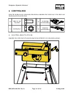
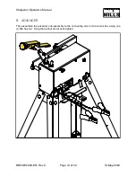
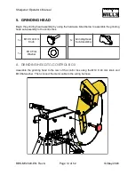
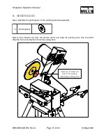
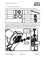
4. CONTROL BOX
Using the hardware and components listed below, assemble the control box to the stand and
the advancer to the control box.
A. CONTROL BOX-TO-STAND
Assemble the control box to the stand using the two (2) M6 X 14 mm hex bolts as shown.
2x
M6 X 14 mm
Hex Bolt
1x
Control Box
Sub-Assembly
1x
M6 Hex Nut
1x
Advancer
Sub-Assembly
BBS-MY2020-EN: Rev A
Page
of
12
52
19-May-2020
Summary of Contents for BANDSAW BLADE SHARPENER
Page 1: ...BANDSAW BLADE SHARPENER OPERATOR S MANUAL BBS MY2020 EN Rev A Publication Date 19 May 2020 ...
Page 2: ......
Page 47: ...Sharpener Operator s Manual CONTROL BOX BBS MY2020 EN Rev A Page of 45 52 19 May 2020 ...
Page 48: ...Sharpener Operator s Manual GRINDING HEAD BBS MY2020 EN Rev A Page of 46 52 19 May 2020 ...
Page 51: ...Sharpener Operator s Manual NOTES BBS MY2020 EN Rev A Page of 49 52 19 May 2020 ...
Page 52: ...Sharpener Operator s Manual BBS MY2020 EN Rev A Page of 50 52 19 May 2020 ...
Page 53: ...Sharpener Operator s Manual BBS MY2020 EN Rev A Page of 51 52 19 May 2020 ...
Page 54: ...Sharpener Operator s Manual BBS MY2020 EN Rev A Page of 52 52 19 May 2020 ...
Page 55: ......
Page 56: ......


