background image

-11-

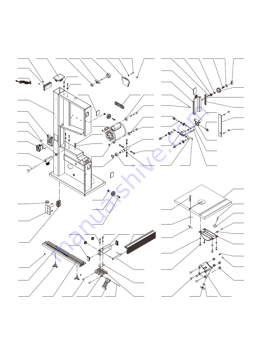
7. DIAGRAMS & COMPONENTS

14

15

26

20

21
22

23

24

25

27
28

19

18

37
38

17

16

13

12

1

2

3
4
5
6
7

9

10

11

8

40

29

30

31

32
33

34
35
36

41

53
52

45

42

44

43

46

155

156

157

158

34

51

48

47

50

49

159

160

161

162

-12-

75

59

71

70

69

68

67

66

65

76

72

64

61

62

63

60

88

86

87

80
81

132

133

135
134

136

153

149

148

147

141

142

143

144

145

146

150
151
152

139

140

138
137

79

78

82

131

130

154

84

85

83

54

126
127

129

128

125

103

104

105

113

109

108 107 106

112

110
111

102

101

100

99

91

90

89

123
122
121

124

120
119
118
117
116

98

95

96

77

94

93

92

97

56
55

58
57

115

114

74

73

Summary of Contents for BS250B

Page 1: ...n Manual IMPORTANT For your safety read instructions carefully before assembling or using this product Save this manual for future reference Original Instruction V 1 201807 BANDSAW BS250B The Aussie Muscle Series ...

Page 2: ... COMPONENTS 3 2 TECHNICAL SPECIFICATION 3 3 ELECTRICAL CONNECTION 3 4 NOISE LEVEL 3 5 DUST EXTRACTION 3 6 SAFETY DEVICES 4 INSTALLATION 4 1 INSTALLATION ZONE CHARACTERISTIC 4 2 INSTALL OF LOOSE PARTS INTRODUCTION 5 ADJUSTMENT AND OPERATION 5 1 CENTERING TABLE AND TILTING 5 2 SETTING TABLE SQUARE WITH BLADE 5 3 CHANGING AND SETTING THE BLADE 5 4 BLADE GUIDING 5 5 SETTING CUTTING HEIGHT 6 TROUBLE SH...

Page 3: ...tant operations For a quick research of the topics it is recommended to consult the index To better stress the importance of some basic passages they have been marked by some preceding symbols 1 2 MACHINE IDENTIFICATION There is a identification plate fixed to the machine containing the manufacturer s data year of construction serial number and technical specifications 1 3 CUSTOMER SERVICE RECOMME...

Page 4: ...ks knots metal parts etc Never place hands among the moving parts and or materials Keep hands clear from the tool feed the piece with the aid of a pusher Keep the tools tidy and far away from those not authorized persons Never employ cracked nor uckled neither not correctlyreground tools Never use the tools beyond the speed limit recommended bythe producers Carefully clean the rest surfaces of too...

Page 5: ...risks Use the appropriate care and concentration for any type of machining also the most simple The highest safety is in your hands 2 3 SAFETY AND INFORMATION SIGNALS This signals may be applied on the machine in some cases they indicate possible danger conditions in others they serve as indication Always take the utmost care SAFETY SIGNALS Risk of eye injury Wear eye protection Wear hearing prote...

Page 6: ...ob 10 Upper wheel 11 Lifting knob 12 Rip fence 13 Dust port 14 Motor SPECIFICATION Motor voltage 230V 50HZ 120V 60HZ Motor power 200W 1 3HP Blade length 1790mm Blade width 6 13mm Max cut depth 120mm Throat width 245mm Blade speed 460 1000m min Table size 350x318mm Table tilt 0 45 Table height to floor 368mm BAS250 SPECIFICATION BS250B Motor voltage 220V 240V 50Hz Power 1 2HP 1 2 3 4 5 6 7 8 9 11 1...

Page 7: ...el Although there is a correlation between the emission levels and the exposure levels this cannot be used reliably to determine whether or not further precautions are required The factors which affect the actual level of operator exposure include the duration of exposure the ambient characteristics and other sources of emission for example the number of machines and other adjacent machining The p...

Page 8: ...o install the machine in explosive environments The installation zone must be selected evaluating the work space required depending on the dimension of the pieces to be machined and taking into account that a free space of at least 800 mm must be left around the machine It is also necessary to check The floor capacity and its surface so that the machine base is evenly resting on its four supports ...

Page 9: ...to table 5 ADJUSTMENT AND OPERATION WARNING Handle the tools with protective gloves 5 1 CENTERING TABLE AND TILTING Centering table can be adjusted Loosen the four bolts which hold the lower table trunnion and adjust freely Place the blade in the middle of the faucet and make it be parallel to the slotted side of table The table can be tilted from 0 to 45 degree To tilt loosen the wing nut A of th...

Page 10: ...econd revolve the upper wheel and adjust handlebar B To place the blade in the middle or front of the cushion rubber Then lock the special nut of handle B 5 4 BLADE GUIDING The saw blades guide of this band saw ensure an exact guiding of the blade for clean cuts When using narrow blades ensure that the lower blade guide positively supports the blade from both sides and the rear Set the bearings of...

Page 11: ...ter gauge Blade wanders during cut 1 Fence not aligned with blade 2 Warped wood 3 Excessive feed rate 4 Incorrect blade for cut 5 Blade tension not set properly 6 Guide bearings not set properly 1 Check and adjust fence 2 Select another piece of wood 3 Reduce feed rate 4 Change blade to correct type 5 Set blade tension according to blade size 6 Review guide bearing adjustment on pages 8 9 Saw make...

Page 12: ... 7 DIAGRAMS COMPONENTS 14 15 26 20 21 22 23 24 25 27 28 19 18 37 38 17 16 13 12 1 2 3 4 5 6 7 9 10 11 8 40 29 30 31 32 33 34 35 36 41 53 52 45 42 44 43 46 155 156 157 158 34 51 48 47 50 49 159 160 161 162 ...

Page 13: ...34 136 153 149 148 147 141 142 143 144 145 146 150 151 152 139 140 138 137 79 78 82 131 130 154 84 85 83 54 126 127 129 128 125 103 104 105 113 109 108 107 106 112 110 111 102 101 100 99 91 90 89 123 122 121 124 120 119 118 117 116 98 95 96 77 94 93 92 97 56 55 58 57 115 114 74 73 ...

Page 14: ... Washer WSH6GB97D1B 4 82 Nut M6GB6170B 4 135 Screw M4X16GB70D1B 2 29 Shaft plate JMBS0901040008 001Z 1 83 Nut M14GB6171Z 1 136 Screw M5X10GB70D2B 2 30 Nut M6GB6177D1B 4 84 Retaining ring CLP12GB894D1B 2 137 Guide plate JMBS1001010001 1 31 Screw M6X10GB77B12D9 2 85 Washer JL45060008 1 138 Rack JMBS1001050001 1 32 Motor Pulley JMBS1001020002A 1 86 Nut M6GB6170B 1 139 Square bolt M6X50GB12B 1 33 Poly...

Page 15: ......

Reviews: