Maintenance & Troubleshooting
Wiring Diagram
CBNdoc080917
6-1
6
SECTION 6 MAINTENANCE & TROUBLESHOOTING
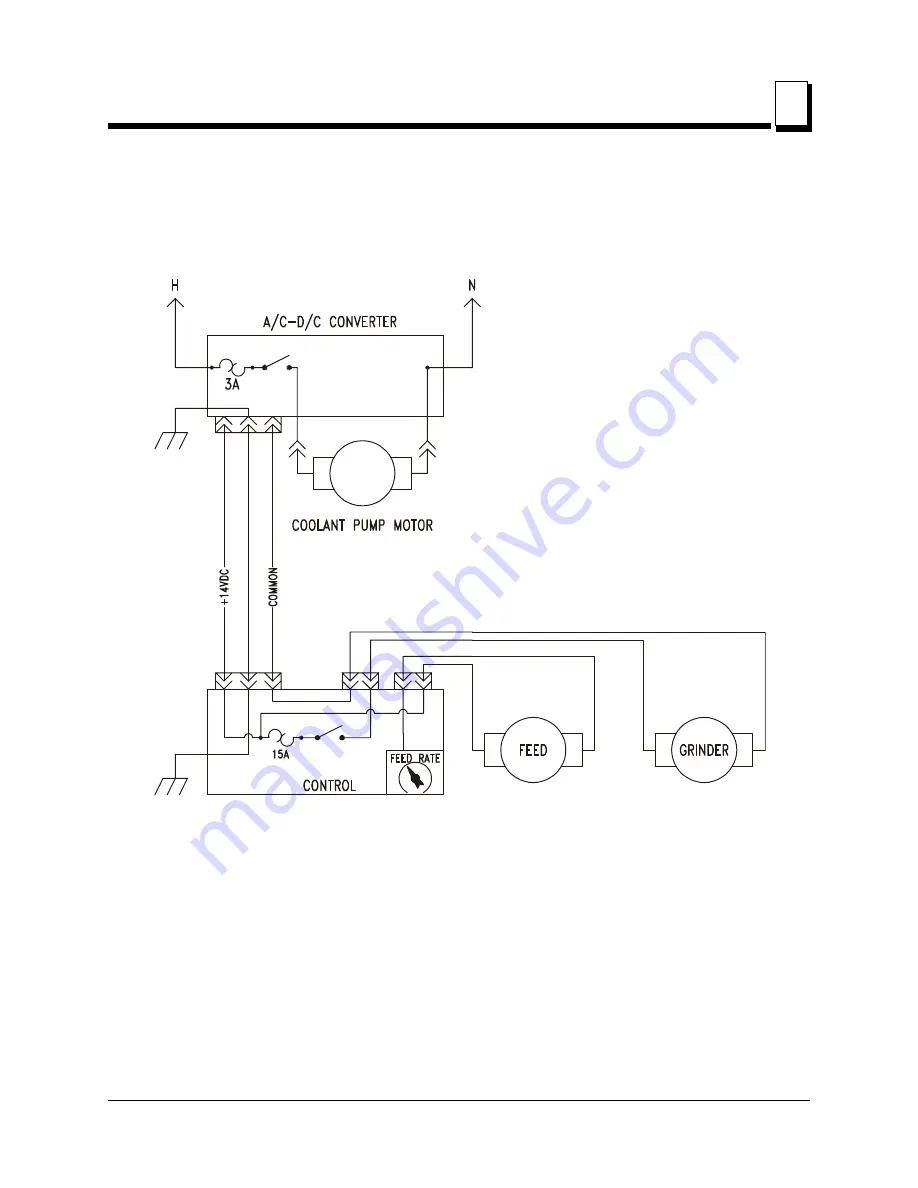
6.1
FIG. 6-1
SH0008B
(See Converter Diagram for detail)
Page 1: ...LTAGA CBN rev B 01 LTAGA FCBN rev B 01 Safety is our 1 concern Read and understand all safety information and instructions before oper ating setting up or maintaining this machine Form 841...
Page 2: ...lamp Optional Blade Clamp 2 9 Blade Installation 2 17 SECTION 3 SHARPENER ADJUSTMENTS 3 1 3 1 Overview Of Adjustments 3 1 3 2 Face Grind and Depth Back Grind Adjustments 3 2 SECTION 4 SHARPENER OPERAT...
Page 3: ...ts CBNdoc080917 iii SECTION 6 MAINTENANCE TROUBLESHOOTING 6 1 6 1 Wiring Diagram 6 1 6 2 Converter Diagram w P09743 Transformer 6 2 6 3 Converter Diagram w 073573 Transformer 6 3 6 4 Sharpener Mainten...
Page 4: ...igned for light duty profile grinding of Wood Mizer blades only 2 This grinder cannot be used to convert the tooth profile more than would require a 020 change in tooth height Blades with 4 can be cha...
Page 5: ...and observe any applicable safety instructions includ ing dangers warnings and cautions Always be sure that all safety decals are clean and readable Replace all damaged safety decals to prevent perso...
Page 6: ...TION Remove the grinding wheel while transporting the Sharpener to prevent damage due to jarring or bumping of the unit CAUTION Do not run the pump until it is under oil Dry operation will damage the...
Page 7: ...k Grind Adjustment Knob Controls how far the grinding wheel comes down against the gullet and back side of teeth 8 Magnetic Shut off Sensor Automatically turns off grinder and cam motors by sensing ma...
Page 8: ...arts listed above are not included as they were already provided with the original sharpener Bag Assembly Contents Qty Magnet Orange Shutoff 3 Plug Rubber Stop 1 Fitting 3 8 x 1 4 FPT Hose 1 Roller Bl...
Page 9: ...tting height or standing height See Figure 2 1 For sitting setup insert the three long stand legs into the sockets in the top of the stand tray For a standing setup add the three short stand legs to t...
Page 10: ...ly dealer for various brands of GFI s CAUTION Do not run the pump until it is under oil Dry operation will damage the pump CAUTION Use the 110 Volt AC output to power the coolant pump of the Wood Mize...
Page 11: ...nto a grounded receptacle 4 Oil is pumped from the oil pan through the oil flow control valve to the grind area IMPORTANT Be sure the rubber stop is properly installed before filling the oil pan Fill...
Page 12: ...ugh extension and longer mounting bolts are supplied Remove the existing oil trough mounting bolts Place the extension plate between the existing oil trough and mounting plate Use the longer 2 1 4 bol...
Page 13: ...indicating that the pump is operating 3 With the FEED RATE all the way down push the START button on the control box This turns on the cam motor 4 Flip the GRINDER switch on The sharpener motor shoul...
Page 14: ...ade support assembly includes three blade support arms and three blade support guide assemblies See Figure 2 5 Lubricate the threaded ends of the three blade support arms with grease Insert a blade su...
Page 15: ...bolts a keps nut and a wing nut Join a blade support guide assembly onto the ends of the left and rear blade support arms with posts facing outward as shown Bolt from the hexed side of the guide assem...
Page 16: ...onto the end of the blade support arm post facing inward as shown Continue assembly as above Tilt the guide on the left blade support arm slightly backward toward the rear of the sharp ener and adjust...
Page 17: ...the head angle will need to be checked Remove the roll pin and follow the procedure below If necessary drill a new hole to reinstall the pin See Figure 2 8 To adjust sharpener head angle place the ang...
Page 18: ...the vertical plate of the sharpener Tip the sharp ener head until the full length of the motor housing contacts the full length of the template edge Hold the sharpener head in place while retightenin...
Page 19: ...r motor is OFF Cycle the cam until the grinding wheel is at the tip of the tooth about to begin face grind 2 Remove the grinding wheel cover oiler assembly and sharpener arbor nut Remove the grinding...
Page 20: ...points Secure in position by tightening the clamp adjustment bolt See Figure 2 11 7 Remove the arbor nut and alignment tool 8 Reinstall the grinding wheel and secure in place with the arbor nut 9 Rei...
Page 21: ...over and the oiler assembly See Figure 2 12 Remove the arbor nut from the motor shaft Slide a grinding wheel onto the shaft Replace the arbor nut with the machined or grooved side toward the grinding...
Page 22: ...the clamp plates See Figure 2 13 Use the upper set of holes for 1 blades the middle set of holes for 1 1 4 blades and the bottom set of holes for 1 1 2 blades Replace the lock nuts Tighten the nuts on...
Page 23: ...ve the nut on each rest bolt and move the bolts to one of the five sets of holes in the clamp plates See Figure 2 14 Use the upper set of holes for 1 blades the next set of holes for 1 1 4 blades the...
Page 24: ...t is at the 2 o clock position Uncoil a blade and position above the three support assemblies around the sharpener Check to be sure the teeth on the portion of blade that will be under the grinding wh...
Page 25: ...he sharpener head Make final adjustments to blade support arms and guide assemblies to assure the blade band rests evenly on both the right and left hardened dowel pins located in the blade clamp asse...
Page 26: ...perational The sharpener head should be set at the proper hook angle At this point in the instructions you should have your sharpener completely assembled and operational the sharpener head set at the...
Page 27: ...ce grind after adjusting depth grind will change the amount of grind on the back side of the tooth As you operate the sharpener the cam will rotate causing the index arm to contact a tooth and push it...
Page 28: ...turn the face grind adjustment knob out away from the other knob If the face grind is too heavy turn the adjustment knob in toward the other knob To adjust depth back grind turn the depth back grind...
Page 29: ...ore grinding This will assist you in seeing how the grinding wheel is contacting the tooth so you can make the appropriate adjustments 5 Index the blade a half rotation and inspect the gullet Confirm...
Page 30: ...lts NOTE A bottle of red dye is supplied Brush the tooth with die before grinding This will assist you in seeing how the grinding wheel is contacting the tooth so you can make the appropriate adjustme...
Page 31: ...gnet it automatically shuts down the grinder and cam motors of the LTAGA To install take an orange painted magnet from the bag assembly Place the black side of the magnet against the bottom edge of th...
Page 32: ...e cam pivot bolt is at the 2 o clock position Lift the sharpener head with your right thumb and the indexing arm with your right fingers in that order Use your left hand to remove the blade from the s...
Page 33: ...S04444 4 is not available except in subassembly A03333 Subassembly K05555 includes parts M06666 and F07777 77 The diamond indicates M06666 is not available except in subassembly K05555 To Order Parts...
Page 34: ...UMBER QTY 1 BRACKET AUTOMATIC SHARPENER MOUNTING W09766 1 2 BOLT 1 4 20 X 3 4 HEX HEAD FULL THREAD F05005 1 4 3 NUT 1 4 20 SELF LOCKING F05010 9 4 4 TRAY WATER COOLANT W09769 1 5 PLUG RUBBER WATER TRA...
Page 35: ...1 6 Washer 1 4 Retainer P10614 1 7 Bolt 1 4 20 x 1 1 2 Hex Head Grade 2 F05005 5 6 8 Nut 1 4 20 Self Locking F05010 9 3 9 Nut 1 4 20 Wing F05010 13 3 Instruction Sheet Blade Support Guide Assembly A1...
Page 36: ...5 1 1 Clamp Assembly CBN Profile LTAGA 010761 1 1 Plate Moving Clamp S10652 1 2 Nut 3 8 24 UNC Hex Jam F05010 22 4 3 Washer 3 8 Flat F05011 3 2 4 Spring Clamp Handle LC 067GH 4SS P09818 2 5 Stud 3 8 2...
Page 37: ...5 2 21 Washer 1 4 SAE Flat F05011 11 2 22 Nut 1 4 20 Nylon Lock F05010 69 2 23 Bracket Oil Trough Mounting 010735 1 24 FITTING 1 4 NPT BRASS TEE 010720 1 25 FITTING 1 4 NPT HEX NIPPLE P09144 1 26 FITT...
Page 38: ...o allow higher range of movement for grinding head 1 1 Plate AGA Moving Clamp 060189 1 2 Nut 3 8 24 UNC Hex Jam F05010 22 4 3 Washer 3 8 Flat F05011 3 2 4 Spring Clamp Handle LC 067GH 4SS P09818 2 5 S...
Page 39: ...tment S09733 2 2 Adjustment Weldment Pawl 010702 1 3 Spring Index Arm LC 045G 7SS P09816 1 4 Bushing 3 4 Long Flanged 004653 1 5 Pin 1 8 x 3 4 Roll F05012 6 1 6 Arm Weldment Cam Index 010742 1 7 Washe...
Page 40: ...AD GRADE 2 F05006 5 1 24 NUT 5 16 18 HEX F05010 17 1 25 BRACKET MAGNETIC SHUTOFF SWITCH MOUNT S09838 1 26 SWITCH MAGNETIC SHUTOFF A10514 1 27 MAGNET ORANGE SHUTOFF S10519 1 3 CAM ASSEMBLY CBN PROFILE...
Page 41: ...A04665 1 Motor Assembly 12 Volt DC w Harness A10701 1 Motor 12 VDC 016706 1 Brush Kit Leeson Motor External 034002 Connector 2 Pin E10551 1 Contact Wire Pin E10552 2 Tube 3 8 Neoprene R01897 2 ft Ter...
Page 42: ...9 29 7 8 TOOTH SPACE 220 TOOTH HEIGHT CBN PROFILE GRINDING 030380 1 WHEEL 10 30 7 8 TOOTH SPACE 250 TOOTH HEIGHT CBN PROFILE GRINDING 030381 1 WHEEL 13 29 7 8 TOOTH SPACE 300 TOOTH HEIGHT CBN PROFILE...
Page 43: ...A09765 1 1 Rod Back Grind Screw S09701 1 2 Knob Back Grind Screw S09733 1 3 Pin 5 32 x 1 Hardened Dowel F05012 28 1 4 Spring Back Grind LC 045G 7SS P09816 1 5 Block Back Grind Knob Trunnion S09730 1...
Page 44: ...13 Spring Lift Arm LE 031C 8SS P09817 1 14 BOLT 5 16 18 X 1 HEX HEAD F05006 1 2 15 NUT 5 16 18 HEX LOCK F05010 6 2 16 END 5 16 24 MALE ROD P09814 1 17 NUT 5 16 24 HEX F05010 28 1 18 END 5 16 24 FEMALE...
Page 45: ...31 220 1 1 Cover AGA Transformer S10487 1 2 Base AGA Transformer S10488 1 3 Decal GFI 110V Transformer Danger P10526 110 1 Decal GFI 220V Transformer Danger P10526 220 1 4 Transformer 250VA 120 240V 1...
Page 46: ...473 1 Instruction Sheet Switch Replacement A10703 495 1 12 Harness Assembly LTAGA Power Supply DC Out 053328 1 13 Breaker 3 Amp Circuit 110V Transformer E10466 1 Breaker 2 Amp Circuit 220V Transformer...
Page 47: ...ol Box S10522 1 2 Base AGA Control S10694 1 3 Screw 8 x 5 8 Phillips Pan Head A F05015 3 4 4 Breaker 15 Amp Circuit E10698 1 5 Connector 2 Pin Tapered E10483 1 6 Connector 2 Pin Rectangle E10480 1 7 C...
Page 48: ...08 10R 1 13 Switch AGA Speed Control E20519 1 14 Knob Speed Control P06257 1 15 Washer 1 4 I D Lock F05011 37 2 16 Switch AGA Black Start E10472 1 17 Switch AGA Red Stop E10471 1 18 Circuit Board AGA...
Page 49: ...NT SPLASH 010736 1 5 HANDLE WITH BOLTS P08065 1 6 Bolt 8 32 x 3 8 Self Tapping F05015 8 2 7 SCREW 10 24 X 1 2 UNSLOTTED INDUSTRIAL HEX HEAD MACHINE F05004 27 2 8 SCREW 3 8 16 X 1 HEX HEAD CAP F05007 7...
Page 50: ...ION Indicates Parts Available In Assemblies Only PART NUMBER QTY 1 HARNESS AGA TRANSFORMER CONTROL A10532 1 2 STRAP 1 4 X 6 TIE F05089 1 6 3 TEMPLATE 15 HEAD ANGLE 060246 1 4 OIL 5 GALLONS 165 CE GRIN...
Page 51: ...Maintenance Troubleshooting Wiring Diagram Maintenance Troubleshooting CBNdoc080917 6 1 6 SECTION 6 MAINTENANCE TROUBLESHOOTING 6 1 Wiring Diagram FIG 6 1 SH0008B See Converter Diagram for detail...
Page 52: ...2 SH0055 C B S C B S 220VAC LTAGA Transformer Assembly w P09743 Transformer 110VAC LTAGA Transformer Assembly w P09743 Transformer 110VAC Breaker On Off Toggle Transformer Rectifier Not Used 220VAC B...
Page 53: ...r Assembly w Transformer To Coolant Pump 110VAC J1 C B S Breaker On Off Toggle Transformer Rectifier To Coolant Pump 220VAC J1 C B S Breaker On Off Toggle Transformer Rectifier On Off Toggle Terminals...
Page 54: ...enance Wipe the sharpener dry after each day s use Keep clean of dirt rust and metal filings Remove the clamp regularly and clean out any buildup that might cause it to not clamp the blade firmly When...
Page 55: ...ld otherwise have to be scraped off when it dries Wipe with a clean dry rag Make sure a strong flow of oil flows through the oiler assembly Sharpen the blade when it first shows signs of dullness If t...
Page 56: ...ation 2 3 stand 2 2 C component identification 1 3 M maintenance 6 4 O operation 4 1 blade removal 4 3 blade sharpening 4 1 magnetic shut off 4 2 R replacement parts blade clamp retrofit 5 6 blade sup...