Quick Installation Guide
Industrial 28G L2+/L3 Rackmount
Managed PoE+ Ethernet Switch
RP428/RP628
RP428/RP628 is an industrial grade rackmount 28G switch with
max. 24 Giga PoE+ ports, 4 Giga combo ports and 4x100M/1G
fiber SFP ports, support max. 8 fiber Giga ports help to link more
field switches with long distance fiber connections. The 24 full giga
PoE+ ports, AC plus 2 DC inputs enhance the overall throughput
and power delivery capacities. Rugged design and high EMC
immunity makes RP428/RP628 an ideal solution for industrial
Critical Surveillance applications.
・
Overview
•
1 x Product Unit
•
1 x Power Cord (EU or US type)
•
1 x Quick Installation Guide
Optional Accessory (for detailed information please refer to the
Datasheet)
:
•
1 Gbps SFP Transceiver
・
Package Checklist
www.womaster.eu
Model Name
Description
RP428-AC-P200-
E / -U
Industrial 28G L2+ Managed PoE+ Ethernet
Switch, 24x802.3at PoE+, AC110/220V input, EU
Plug or US Plug
RP428-AC-P200+
2DC54V-E / -U
Industrial 28G L2+ Managed PoE+ Ethernet
Switch, 24x802.3at PoE+, AC110/220V + Dual
54V input, EU plug or US Plug
RP628-AC-P200-
E / -U
Industrial 28G L3 Managed PoE+ Ethernet
Switch, 24x802.3at PoE+, AC110/220V input, EU
Plug or US Plug
RP628-AC-P200+
2DC54V-E / -U
Industrial 28G L3 Managed PoE+ Ethernet
Switch, 24x802.3at PoE+, AC110/220V + Dual
54V input, EU plug or US Plug
Note: Please contact WoMaster Sales.
*
AC with higher PoE Budget by Request.
*2DC/2AC Version By Request
*Other type plug of Power Cord by Request
・
Installation Procedure
Wiring the Power Input
Connect the attached power to the AC or DC power input connector, the
available AC power input range is from 90-264 VAC while the DC power
input is
54VDC.
Wiring the Digital Input
To wire the DI on the Terminal block, use
screwdriver to loosen screws, insert the positive
and negative wires into the DI+ and DI- contact
and then tighten screws after the DI wire is
connected. High: 11~30V, Low: 0~10V.
DI
Wiring the Relay Output (Alarm)
The relay output of the 2-pin terminal block
connector are used to detect user-configured
events. The two wires attached to the fault
contacts form a close circuit when a user-
configured event is triggered. If a user-configured
event does not occur, the fault circuit remains
open. The spec. of DO is 0.5A/24VDC.
DO
・
Appearance
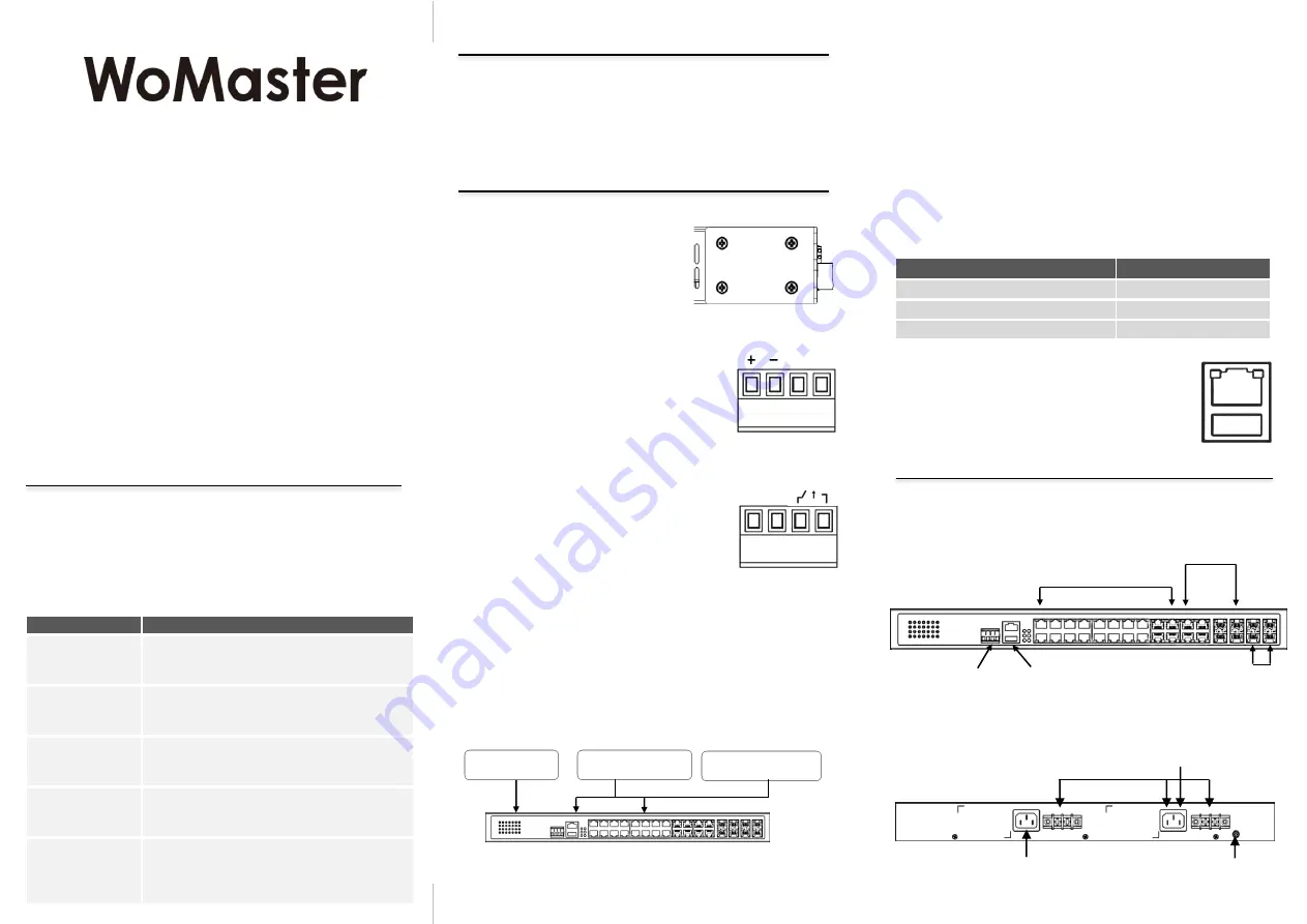
Front Panel Side
USB Port
Use the USB port in order to save or restore
the configuration and upload the firmware
upgrade file.
For further configurations, please refer to User
Manual.
Console
115,200,
N,8,1
USB
Port Mode
COMBO Port 21-24
20GbE 8 GbE Fiber (Default)
4 x Fiber
24GbE 4 GbE Fiber
4 x Copper
22GbE 6 GbE Fiber
2 x 2 x Fiber
Installing in a Rack
Refer to the illustrations below; user can
install the device in most standard 19-
inch (48.3-cm) racks. User should use
the 4 of supplied screws to attach a
mounting bracket on each side of device
first. And insert and tighten two screws
through each of the mounting brackets.
Easy System Management
• USB for
Configuration/Firmware
update
• RS232 Console
System LED
• 2 x Power
• 1 x System Status
• 1 x DI
• 1 x Alarm
• 1 x Ring Status
• 4 x PoE loading
• 24 x PoE Status
Integrated DI/DO Connector
• 1 x 4 pin terminal block
2 pin for DI
2 pin for DO
• 20-port 100/1000MBase-T
• 4-port 100/1G RJ45/SFP
combo (configured by UI)
SFP Port
• 4-port
100M/1G
SFP
Back Panel Side
AC Power & DC Power
for RP628/428-AC+2DC
2nd AC Power Reserved
for 2AC model
Grounding Screw
for DC model
AC Power for RP628/428-AC
Combo Port Mode
The device supports 4 Combo ports and allow user to configure 3 types
of port modes in the following path.
Ethernet Port -> Port Setting -> Port Mode
Select
the Port Mode type and press “Submit”. After submitted, Reboot
the system to activate the new setting.
For further configurations, please refer to User Manual.
Aggregated PoE Source
AC+2DC Aggregated Input (Fixed 54VDC in DC Input).
Aggregated PoE Budget: AC + DC1 + DC2 (Up to 600W)
54V
54V
Rackmount AC
PSU
Rackmount DC PSU
or Desktop DC PSU
Rackmount DC PSU
or Desktop DC PSU
Adjust Power Output to Fixed 54V
(Build-in AC
to 54V PSU)
Grounding Screw
For avoiding system damage by noise or electric shock, establish a
direct connection between the ground screw and the grounding
surface prior to connecting devices. At the AC power input, the 3 pin
include V+, V- and GND. For DC version, the grounding screw is on
the right side of DC power connector. The GND pin must be
connected to the earth ground.


