

・
Management
・
Safety Precautions
.
Turn off DC power input source before connecting the DC Power supply
module to the terminal block connectors. Do not turn-on the source of
DC power module and make sure all connections were well established,
then power on the DC source to powering the Switch device.
.
Do make sure that models connect to the corresponding supply voltage.
The device is to be supplied by Limited Power Supply.
.
The switch must be installed at Restricted Access Locations. The switch
is designed for Railway/Train on-board application.
.
Do not touch the surface of the switch while it is performing PoE
function!
This device supports both in-band and out-of-band network management.
The user can either configure the device through the user friendly
Web/HTTPS management or remotely manage the device through the
network by console management or Telnet/SSH.
1. Preparation for
Web management
: First of all, verify that device is
properly installed in the network and that every PC of this network can
access the switch through the web browser (Google Chrome, Internet
Explorer or Mozilla Firefox).
・
Type
http://IP_address
in your browser (the default IP address is
http://192.168.10.1/
)
・
Key in the user name and password in login screen. The default user
name and password is
admin
.
・
After you click OK, the Welcome page of the web-based management
interface will appear.
・
On the left side you can see the list of software features, on the right
side – available settings.
。
To link with the device, please make sure that the IP Address of the PC
is located in the same subnet (
192.168.10.x
).
2. Preparation for
Telnet/SSH management:
You can connect to the
device by Telnet and the command lines are the same as what you see by
console management. Below are the steps to open Telnet connection to the
switch.
・
Start -> Open Command prompt ->Enter
・
Type the Telnet 192.168.10.1 (or the IP address of the switch). And then
press Enter.
SSH (Secure Shell)
The device also supports SSH console. You can remotely connect to the
switch to access command line interface. The SSH connection can secure
all the configuration commands you sent to the switch.
SSH is a client/server architecture while the Switch is the SSH server.
When you want to make SSH connection with the switch, you should
download the SSH client tool first.
・
Warranty
・
Disclaimer
・
Support
At WoMaster, you can use the online service forms to
request the
support
. The submitted forms are stored in server for WoMaster team
member to assign tasks and monitor the status of your service. Please
feel free to write to
if you encounter any problems.
5-year Global warranties
are available for WoMaster products assuring
our customers that the products shall remain free from defects in
workmanship or materials and conform in all material respects to WoMas-
ter specifications, or Purchaser’s supplied and accepted specifications.
The warranty is limited to the repair and/or replacement, at WoMaster sole
discretion, of the defective product during its warranty period. The custom-
er must obtain a
Return Merchandise Authorization (RMA)
approval
code prior to returning the defective Product to WoMaster for service. The
customer agrees to prepay shipping charges, to use the original shipping
container or equivalent, and to insure the Product or assume the risk of
loss or damage in transit. Repaired or replaced products are warranted for
ninety (90) days from the date of repair or replacement, or for the remain-
der of the original product's warranty period, whichever is longer.
SSH Client
There are many free, sharewares, trials or charged SSH clients you can
find on the internet.
。
For further feature configurations, please refer to User Manual.
WoMaster reserves the right to make changes to this QIG or to the
product hardware at any time without notice. It is the user’s responsibility
to determine whether there have been any such updates or amendments
herein.
Defects, malfunctions, or failures of the warranted Product(s) caused by
damage resulting from unforeseeable incidents (such as lightings, floods,
fire, etc.), environmental and atmospheric disturbances, other external
forces such as power line disturbances and surge, host computer
malfunction and virus, incorrect power input, or incorrect cabling, incorrect
grounding and damages caused by misuse, abuse and unauthorized
alteration or repair are not warranted.
www.womaster.eu
© WoMaster Inc. All rights reserved.
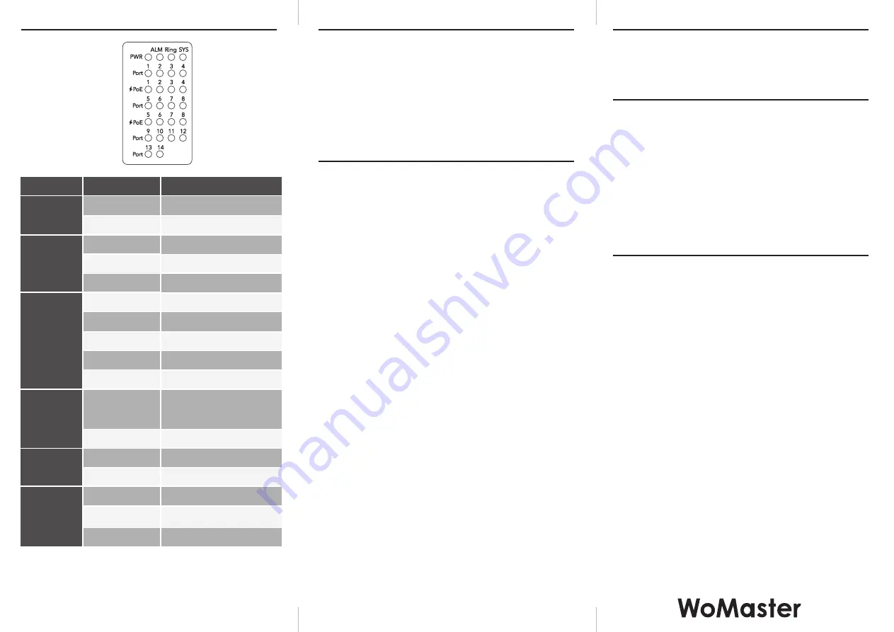
・
LED Indication
LED
PWR
System LED
Ring LED
Status
Green On
Off
Off
Off
DC-IN Power is On
No Power in DC-IN
Alarm
Amber On
Off
PoE is delivered
PoE is Disabled
PoE LED
(Port 1-8)
Green On
Green Blinking
Links established
Packets transmitting/receiving
Green On
Green Blinking
Amber Blinking
Amber On
Ring Normal (Not RPL Owner)
Ring Normal (RPL Owner)
Ring Abnormal
Ring Port Fail
Ring Disabled
Green On
Green Blinking
Ready
Firmware Updating
Not Ready
Ethernet
LNK/ACT
(Port1-14)
Off
Link is inactive
Off
Red On
Any failures in port link, ping,
ring, DO and power by
SW control
No failure occurs
Description
V1.0 Apr 30, 2018 3160-0MP6140-00


