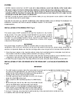


WIRING SWITCH CONTROL PANEL TO 12-24 VOLTS. Fig. F
WARNING: The power supply has an external 5-amp
fuse to protect its internal circuit. The 5-amp in-line
fuse attached to the red wire must be connected “AT A
POWER SOURCE” so to protect the wire connection
between the power source and power supply.
20. BLACK WIRE: Is connected to ground (-). Secure
the BLACK to the negative battery post or under any
metal body bolt. Make sure that the METAL surface
around the bolt that secures the wire is clean of rust
and paint so to make a good electrical connection.
21. RED WIRE: Is connected to 12-24 volts (+) positive.
Using the inline fuse provided, connect the red wire
to the vehicle’s fuse block or (+) positive battery
post. Remove fuse from the inline fuse holder until
all wiring is completed.
22. The plug with the YELLOW wire is connected to the power supply in the position marked “CONTROL’’.
23. The plug with the RED & BLACK wires is connected to the power supply in the position marked
“12-24 VOLTS”.
24. Inspect all wiring and make sure all connections are secure. Install fuse back into the inline fuse holder.
INSTALLATION IS COMPLETE
Position the on/off switch to “ON“. Press and release the push button to change the light pattern.
PATTERN HEAD
HEAD
HEAD
HEAD
LED
HEAD
SEQUENCE
1 2
3 4
1 STEADY
STEADY
STEADY
STEADY
ALL
2 STEADY
STEADY
DF
DF
CONTINIOUS
3 DF DF STEADY
STEADY
CONTINOUS
4 DF DF
DF DF
ALL
5
SF
SF
SF
SF
1&2 / 3&4 ALTERNATE
6 QF QF
QF QF
ALL
7 TF TF
TF TF
ALL
8
TF
TF
TF
TF
1&2 / 3&4 ALTERNATE
9 TF TF
TF TF
ALL
10 SF SF
SF SF
ALL FAST
11 SF SF
SF SF
ALL
12
DF
DF
DF
DF
1&2 / 3&4 ALTERNATE
13
SF-TF
SF-TF
SF-TF
SF-TF
3-SINGLE FLASHES THEN 3 TRIPLE FLASHES ALTERNATE
14
SF-TF
SF-TF
SF-TF
SF-TF
3-SINGLE FLASHES THEN 3 TRIPLE FLASHES ALTERNATE
15
STF
STF
STF
STF
1&2 / 3&4 ALTERNATE
DESCRIPTION OF LIGHT PATTERN
SF SINGLE
FLASH
DF DOUBLE
FLASH
TF THRIPLE
FLASHES
QF QUAD
FLASH
STEADY
NO FLASH
STF SLOW
TO
FAST
Fig. F


