Wolf CFL-WRG Installation And Maintenance Instructions Manual Download Page 26

26

3065065_201704

2.

1.

3.

4.

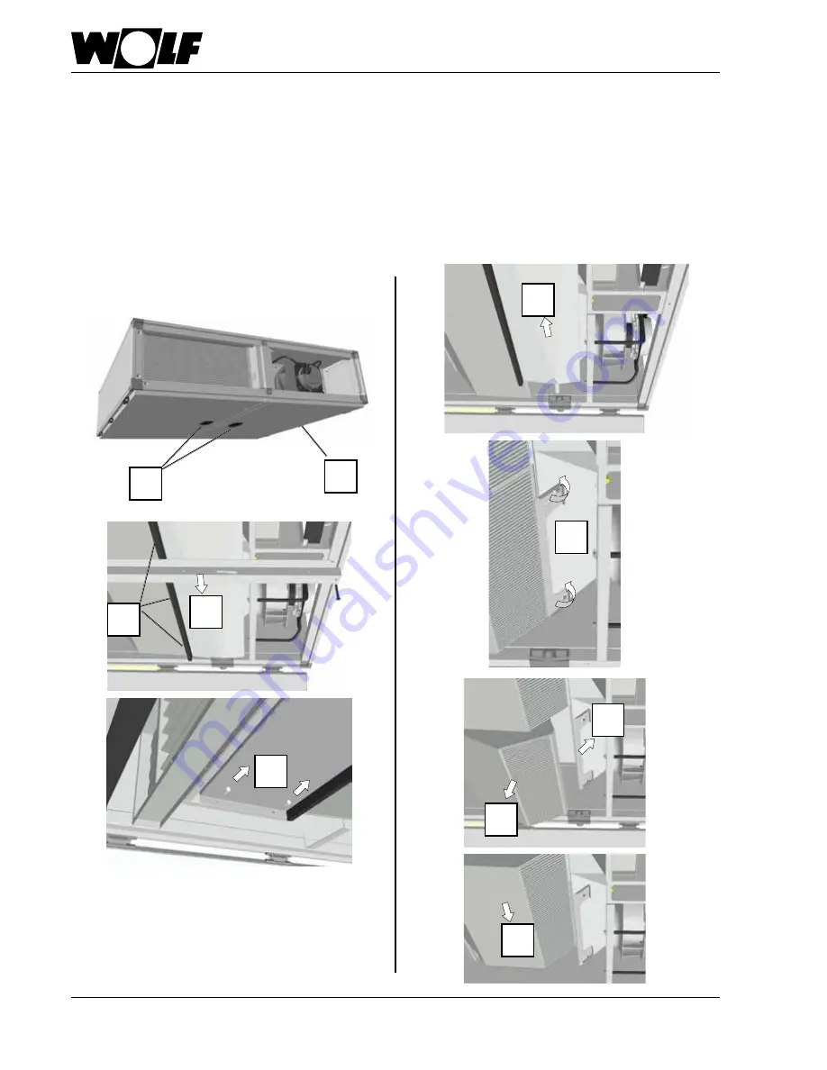
12. Maintenance instructions

5.

6.

7.

8.

1. Disconnect trap drain connection

2. Open inspection doors

3. Undo unit partition screws and remove partition

4. Remove seals (sealant) from condensate pan and condensate drain

5. Undo condensate pan threaded connection

6. Remove condensate pan by lowering slightly (side where screws have been removed) and pulling

7. Slightly loosen tensioning bracket screws

8. Push tensioning bracket upwards

9. Remove first part of countercurrent plate heat exchanger

10. Push further parts along the guide and remove them as well

11. Reassemble in reverse order (re-establish seal with sealant)

1.

2.

3.

5.

6.

7.

8.

4.

CFL 10 / 15 / 22

10.

9.

Summary of Contents for CFL-WRG

Page 1: ...49 0 87 51 74 0 FAX 49 0 87 51 74 16 00 www WOLF eu Document no 3065065_201704 Subject to modifications GB IE Installation and maintenance instructions CFL WRG Comfort slimline ventilation unit Trans...

Page 2: ...ication 9 6 Delivery handling 10 7 Installation siting 11 14 Installation location 11 Louver dampers 12 Servomotors 12 Duct connections 12 Trap 13 Minimum clearances 13 Hydraulic connection 14 Air con...

Page 3: ...rence symbols are used in these instructions This important information concerns personal and operational safety as well as operational reliability Safety information identifies instructions that must...

Page 4: ...work Only operate the unit within its output range which is stated in the technical documentation supplied by Wolf Only operate the unit if it is in technically sound condition Anyfaultsordamagethatim...

Page 5: ...minals and connections of the EC fans even when the unit has been shut down This means there is a risk of electric shock that could result in injury or death Do not touch the EC fans for five minutes...

Page 6: ...electrical appliances general requirements VDI 3803 Central air conditioning systems Structural and technical principles Furthermore VE regulations and the local building code apply to Austria 3 Stan...

Page 7: ...haust air Extract air Supply air Operating side supply air right supply air left mirror inverted The illustration shows the unit with the connection side on the right in the supply air direction Conne...

Page 8: ...ght A mm 495 Width B mm 1932 Length C mm 1932 Dimensions EC fan supply air Control unit EC fan exhaust air Bypass damper with servomotor variable speed Countercurrent heat exchanger F7 compact filter...

Page 9: ...voltage V 1 x 230 V 1 x 230 V 1 x 230 V 3 x 400 V Frequency Hz 50 60 50 60 50 60 50 60 Max power consumption W 480 750 715 1650 Max current consumption A 2 1 3 3 3 1 2 5 Speed rpm 2970 3450 2800 3140...

Page 10: ...bient temperature between 25 C and 55 C If it is stored for a long time ensure that all apertures are sealed against air and water ingress Delivered condition Transport When transporting units through...

Page 11: ...andard are intended for lifting and turning the unit Never use them for mounting the unit on the ceiling After use the lifting lugs can be removed and the drilled holes sealed with the supplied blanki...

Page 12: ...del size CFL 32 rivet the mounting bracket to the damper Mounting bracket Servomotors CFL 10 15 22 32 Duct connections on site Theconnectorsoftheunitarerectangular Roundductscanbeconnecteddirectly to...

Page 13: ...acc to appliance design 50 mm WC Reserve inaccuracy in design evaporation 1 5 Additional safety factor Do not connect the trap drain line directly to the public sewage system It must be able drain of...

Page 14: ...anger improves the control characteristics 1 2 Cooling coil Hydraulic connection example 7 Installation siting Outdoor air AUL ODA 6801059 48 10 AUL ODA Exhaust air FOL EHA 6801062 48 10 FOL EHA Extra...

Page 15: ...rconnectingon sitecables Voltage is still present at terminals and connections of the EC fans even when the unit has been shut down This means there is a risk of electric shock that could result in in...

Page 16: ...age CFL 10 15 22 Image CFL 32 Entry for on site cables Open bypass inspection door Remove cover plate from control unit and connect cables according to wiring diagrams Check cover plate for leak tight...

Page 17: ...ations and the local building code apply in Austria Before commissioning check whether the operating data specified on the type plate is adhered to The unit must not be operated before all necessary s...

Page 18: ...t parameters To modify functions and parameters see the installation and operating instructions provided Where the system is not commissioned by Wolf check all inputs and outputs for correct wiring an...

Page 19: ...ever operate the CFL below a minimum air flow rate if an electric heating coil is installed Follow the relevant safety regulations for electric heating coils The electric heating coil must be protecte...

Page 20: ...rotect the condensate drain from frost Fill the trap with water Countercurrent plate heat exchanger bypass damper The countercurrent plate heat exchanger is generally maintenance free During commissio...

Page 21: ...the outside when conducting the test Due to the installation conditions of the fans K values differing from the manufacturer s specifications must be used for flow rate determination CFL 10 effective...

Page 22: ...Effective pressure p Pa Flow rate m h p Pa 10 20 40 60 85 115 150 190 235 280 V m h 400 600 800 1000 1200 1400 1600 1800 2000 2200 For the CFL 22 use a K value of 131 Effective pressure p Pa Flow rate...

Page 23: ...the fan or even cause a risk to life Voltage is still present at terminals and connections of the EC fans even when the unit has been shut down This means there is a risk of electric shock that could...

Page 24: ...ters never operate the system without filters X Longest filter replacement interval X Air ducts Check accessible air duct sections for damage Repair X Check inner air duct surface for contamination co...

Page 25: ...re restarting replace the factory fitted seal on the condensate pan if this was removed during maintenance on the plate heat exchanger Please note Countercurrent plate heat exchanger PHE Electrical eq...

Page 26: ...in 5 Undo condensate pan threaded connection 6 Remove condensate pan by lowering slightly side where screws have been removed and pulling 7 Slightly loosen tensioning bracket screws 8 Push tensioning...

Page 27: ...ion 2 Open bypass inspection door 3 Remove pan panel connecting screws 3x 4 Undo screws at side of pan panel and remove pan panel 5 Slightly loosen tensioning bracket screws 6 Push tensioning bracket...

Page 28: ...solution Check that the test lead if fitted is seated firmly at the test connector on the inlet nozzle Loose seating can result in faulty measurements The integral installation aid facilitates remova...

Page 29: ...ensate pan for possible soiling and clean if required see checklist Condensate pan CFL 10 15 22 CFL 32 Bypass servomotor The motors are maintenance free At regular intervals check that the connection...

Page 30: ...x D48 1668826 4 F7 compact filter outdoor air W592 x H287 x D48 1668827 5 Differential pressure switch JDL 112 2738360 6 Countercurrent plate heat exchanger GS 30 570 2980929 7 Servomotor for bypass d...

Page 31: ...6 x H842 x D48 1669201 4 F7 compact filter outdoor air W406 x H842 x D48 1669202 5 Differential pressure switch JDL 112 2738360 6 Countercurrent plate heat exchanger GS 45 520 2981955 7 Servomotor for...

Page 32: ...Wolf GmbH P O Box 1380 D 84048 Mainburg Tel 49 0 87 51 74 0 Fax 49 0 87 51 74 16 00 www wolf eu Document no 3065065_201704 Subject to modifications...

Reviews: