background image

11

English

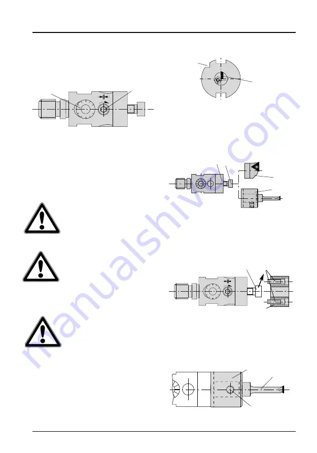
Example: Steep angle taper to 
DIN 69871

c) Securing the adaptor, 

tool holder and insert holder

Adjusting plate 

8

is serrated to enable

different tool holders 

2

and connectors

3

to be mounted quickly and easily 

(figure 4).

– Adaptors 248063 / 248064 / 

248065 / 248071 “Mini“

Remove cap screw 

9

. Secure adaptor 

3

for the tool holder centrally on the adjus -
ting plate (figure 5). Secure the adaptor
using cap screw 

0

. Apply

1,5 Nm

(13.23 in. lbs.) torque.

– Tool holder

Insert tool holder 

4

into adaptor 

3

and

secure using thread pin 

ß

. Apply torque

of 

2,5 Nm

(22.125 in. lbs.) (figure 6).

4. Operation

a) Clamping

To clamp the adjusting pin, all tools are
fitted with a clamping screw 

6

(figure 2).

When removing metal, this clamping
screw 

6

must be used to clamp the

adjusting pin. Before and after each
adjustment, the clamping arrangement
must be operated. Graduated dial 

7

for

the spindle adjustment is located next to
the tool clamping point. Only one key is
needed to operate both functions.

To avoid damage to parts of the

adjustment mechanism, do not

make any diameter adjust-

ments in the clamped state.

b) Fixing the tool to the connector shank

Secure the tool to the shank apply ing

a torque of 20 Nm (177.015 in. lbs.)

Using a higher torque you will

damage the thread M 8.

Service keys see page 13.

To do this, we suggest you to grip the
shank in a collet chuck:

When gripping the shank in the

collet chuck, please take

account of the cutter position

relative to the chuck’s 

grooves or serrations (figure 3).

10

1

5

0

5

7

6

Serration

Indexable
insert

8 9

2

3

10

1

5

0

5

0

9

3

4

3

ß

figure 2

figure 3

figure 4

figure 5

figure 6

Summary of Contents for 248 001

Page 1: ...nstructions Mode d emploi 102 527 08 2013 Ausdrehwerkzeuge für die Fertigbearbeitung Ø 3 0 30 2 mm Boring tools for finish machining Ø 3 0 30 2 mm Ø 0 118 1 189 Outils d alésage pour les travaux de finition Ø 3 0 30 2 mm 248 inch 249 ...

Page 2: ...iption 17 4 Utilisation 18 5 Entretien 20 6 Accessoires 20 7 Pièces de rechange 21 8 Données techniques 22 Wohlhaupter Werkzeuge unterliegen einer ständigen technischen Weiterentwicklung Aktuelle Informationen erhalten Sie aus unseren Produkt Katalogen sowie im Internet unter www wohlhaupter com Wohlhaupter tools are subject to constant further technical development You can obtain up to date infor...

Page 3: ...ufuhr bis zur Schneide zulässiger Druck max 40 bar 1 Sicherheitshinweise Bitte lesen Sie vor Inbetrieb nahme des Werkzeugs die in dieser Bedienungsanleitung aufgeführten Informationen aufmerksam durch Sie geben wichtige Hinweise für Ihre Sicherheit sowie für den Gebrauch und die Wartung des Werkzeuges Dieses Feindrehwerkzeug ist für das Ausspindeln von Bohrungen in metalli schen Werkstoffen konzip...

Page 4: ... Klemmschraube 6 der Verstellbolzen geklemmt sein Vor und nach jedem Verstellvorgang muss diese Klemmung betätigt werden Unmittelbar neben der Werkzeugklemmung ist die Skala 7 der Verstellspindel angeordnet Zur Bedienung beider Funktionen ist nur ein Bedienschlüssel erforderlich Durchmesserverstellung nicht in geklemmtem Zustand vor nehmen Verstellteile werden sonst beschädigt b Befestigung des We...

Page 5: ...tellteile werden sonst beschädigt 1 Zylinderschraube 6 lösen Bild 2 11 2 Werkzeug durch Drehen der Skala 7 auf Durchmesser einstellen auf einem Werkzeug Einstellgerät auf der Maschine mittels Mess schnitt bzw Probebohrung Bei einer Umdrehung der Skala wird der Verstellbolzen und damit die Werkzeugschneide um 0 2 mm im Durchmesser verstellt Ein Teilstrich auf der Skala entspricht einer Durchmesserv...

Page 6: ...0 C Tropfpunkt 190 C zum Beispiel WYNN S MULTI PURPOSE GREASE Schmierfett Bestell Nr 203 107 Service und Reparaturen werden in unserem Werk durchgeführt 6 Deutsch Bild 12 6 Zubehör Zubehör ist nicht im Lieferumfang enthalten und ist separat zu bestellen Hochdruck Stoßfettpresse Best Nr 203 006 Bedienschlüssel Bedienschlüssel Type Best Nr s2 0 A 215 473 s2 5 A 115 575 s3 0 A 115 630 Bedienschlüssel...

Page 7: ...141 s2 5 S 3 Zylinderschraube zur Befestigung der Plattenhalter 1 Klemmschraube 4 Zylinderschraube zur Befestigung des Zwischenstücks 5 Gewindestift zur Klemmung des Klemmhalters 7 Ersatzteile Die für den Verstellmechanismus eingebauten Einzelteile sind präzise aufeinander abgestimmt und daher nicht austauschbar Die vom Anwender austauschbaren Ersatzteile 1 3 4 und 5 siehe Tabellen für die Klemmun...

Page 8: ...ug über Fein Drehzahl Bestell Nr verstellung in 1 min 248 001 1 4 mm 20000 248 002 1 8 mm 15000 248 003 2 3 mm 8000 8 Zwischenstück passend für Zylinderschraube 4 Schlüssel Gewindestift 5 Schlüssel Bestell Nummer Feindrehwerkzeug Bestell Nummer weite Bestell Nummer weite 248 071 248 003 515 166 s2 5 415 244 s3 4 Zylinderschraube zur Befestigung des Zwischenstücks 5 Gewindestift zur Klemmung des Kl...

Page 9: ...uppwerkzeug t mit Funktionsmodul ZV zentrisch verstellbare Plattenhalter t mit Funktionsmodul EV einzeln verstellbare Plattenhalter Vario Line eine anwenderfreundliche Plattform mit vielen Variationsmöglich keiten Mit den Funktionsmodulen einfach über Skala einstellbar Wohlhaupter GmbH Präzisionswerkzeuge Postfach 1264 t 72633 Frickenhausen Tel 49 0 7022 408 0 t Fax 49 0 7022 408 177 www wohlhaupt...

Page 10: ...feed internal coolant feed up to the cutting edge permissible pressure max 40 bar 580 PSI 1 Basic safety information Before first use please read the operating instructions carefully These provide important safety infor mation and information concerning use and maintenance of the tool This precision boring tool is designed for finishing bores in metallic materials Specific information on the machi...

Page 11: ...s clamping screw 6 must be used to clamp the adjusting pin Before and after each adjustment the clamping arrangement must be operated Graduated dial 7 for the spindle adjustment is located next to the tool clamping point Only one key is needed to operate both functions To avoid damage to parts of the adjustment mechanism do not make any diameter adjust ments in the clamped state b Fixing the tool ...

Page 12: ... adjustment 1 Slacken cap screw 6 figure 2 11 2 For the diameter setting adjust the tool by turning the dial 7 either on a tool setting device or by carrying out a trial drilling or gauge cut on the machine One revolution of the dial is equivalent to the adjusting pin and hence also the cutter on the tool undergoing a diameter adjustment of 0 2 mm 01 One division on the dial corresponds to a diame...

Page 13: ...and 356 F Dripping point 190 C 374 F e g WYNN S MULTI PURPOSE GREASE Order number 203 107 Service and repairs will be done in our company 7 6 figure 11 6 Accessories These are not supplied with the tool and must be ordered separately High pressure grease gun Order number 203 006 Service key Service key Order Type number s2 0 A 215 473 s2 5 A 115 575 s3 0 A 115 630 Service key for securing inserts ...

Page 14: ... 141 s2 5 248 065 248 003 249 003 315 801 s2 5 031 141 s2 5 S 3 Cap screw for fixing insert holders 1 Clamping screw 4 Cap screw for fixing the adaptor 5 Thread pin for clamping the tool holder 7 Spare parts The individual parts comprising the adjusting mechanism have been very carefully matched and are not therefore replaceable The spare parts replaceable by the custo mer are 1 3 4 and 5 See the ...

Page 15: ...ment Max boring tool travel speed Order number rpm 248 001 249 001 1 4 mm 055 20000 248 002 249 002 1 8 mm 071 15000 248 003 249 003 2 3 mm 091 8000 Adaptor suitable for precision Cap screw 4 Key size Thread pin 5 Key size Order number fine boring tool Order number Order number 248 071 248 003 249 003 515 166 s2 5 415 244 s3 4 Cap screw for fixing the adaptor 5 Thread pin for clamping the tool hol...

Page 16: ... im Durchmesser t max Drehzahl 16 000 min 1 t Alu Line Kerbzahnschienen mit Platten haltern ab Ø 30 mm bis Ø 208 mm t µ genaue Maßkorrekturen durch Anzeige in der Maschine t automatischer Wuchtausgleich t zentrale Kühlschmierstoffzufuhr bis 40 bar Die neue Generation Feindrehwerkzeuge Wohlhaupter GmbH Präzisionswerkzeuge Postfach 1264 t 72633 Frickenhausen Tel 49 0 7022 408 0 t Fax 49 0 7022 408 1...

Page 17: ...e Lubrification par le centre jusqu à l arête de coupe pression maximale 40 bar 1 Instructions de sécurité et prévention Avant la première utilisation en production lisez atten tivement la notice d utilisa tion et les informations qu elle contient Vous y trou verez des instructions concernant la sécurité la maintenance et l utilisation de l outil Cet outil de précision d alésage est conçu pour l e...

Page 18: ...te 6 figure 2 Pendant l opération d alésage cette vis 6 doit impérativement être bloquée Il est nécessaire de s assurer de ce bloca ge avant et après montage ou réglage A proximité du dispositif de blocage et de réglage se trouve un vernier 7 qui est actionné par une simple clé Attention toujours régler sans blocage la vis de réglage sinon vous risquez d endom mager les pièces du dis positif de pr...

Page 19: ...st le sui vant 1 Desserrer la vis de blocage 6 figure 2 11 2 A l aide du vernir 7 amener l arête de coupe a la position recherchée soit sur un banc de pré réglage soit a partir de l alésage ébauché en posi tion sur la machine Un tour de vernier correspond à un déplacement de 0 2 mm au diamètre Une graduation correspond à une valeur de déplacement de 0 01 mm Une rotation dans le sens des aiguil les...

Page 20: ...xemple WYNN S MULTI PURPOSE GREASE No de cde 203 107 Le service et les réparations sont exclusivement du ressort de Wohlhaupter et exécutés en ses usines figure 11 figure12 6 Accessoires Les pièces accessoires ne sont pas comprises dans les livraisons de base des porte outils Elles sont à commander séparément Pompe à graisse haut pression No de cde 203 006 Clés de service Clé de service No de cde ...

Page 21: ...031 141 s2 5 S 3 Vis à tête cylindri que pour fixation porte plaquettes 1 Vis de serrage 4 Vis à tête cylindrique pour fixation pièce intermédiaire 5 Goupille filetée pour blocage porte outil 7 Pièces de rechange Les pièces constitutives des mécanismes de réglage sont des pièces de précision montées les unes par rapport aux autres Elles ne sont donc pas interchangeables Les pièces interchangeables...

Page 22: ...on de très haute réglage maximale précision 1 min No de cde 248 001 1 4 mm 20000 248 002 1 8 mm 15000 248 003 2 3 mm 8000 Pièce Adaptable à l outil Vis à tête Dim de Goupille filetée 5 Dim de intermédiaire d alésage de très cylindrique 4 la clé la clé No de cde haute précision No de cde No de cde 248 071 248 003 515 166 s2 5 415 244 s3 4 Vis à tête cylindrique pour fixation pièce intermédiaire 5 G...

Page 23: ... www wohlhaupter com Feindrehen in jeder Dimension von 0 4 3255 mm t opto elektronische Verstellwegmessung t Produktivitäts und Qualitätssteigerung durch µ genaue Maßkorrekturen mittels Anzeige direkt in der Maschine t wasser und staubgeschützt gemäß IP65 t einfache Handhabung t Zustellgenauigkeit 2 µ im Durchmesser ...

Page 24: ...ur machining specialists are familiar with the conditions and requirements of all industrial branches they will provide you with expert advice to achieve profitable solutions Du premier contact jusqu à la mise en œuvre dans le monde entier les clients font appel à nos outils et à nos services La présence sur site ou l assistance téléphonique de notre service techni que n est que l un des aspects d...

Reviews: