


3-5
Button Panel Maintenance
16-020834-00
3
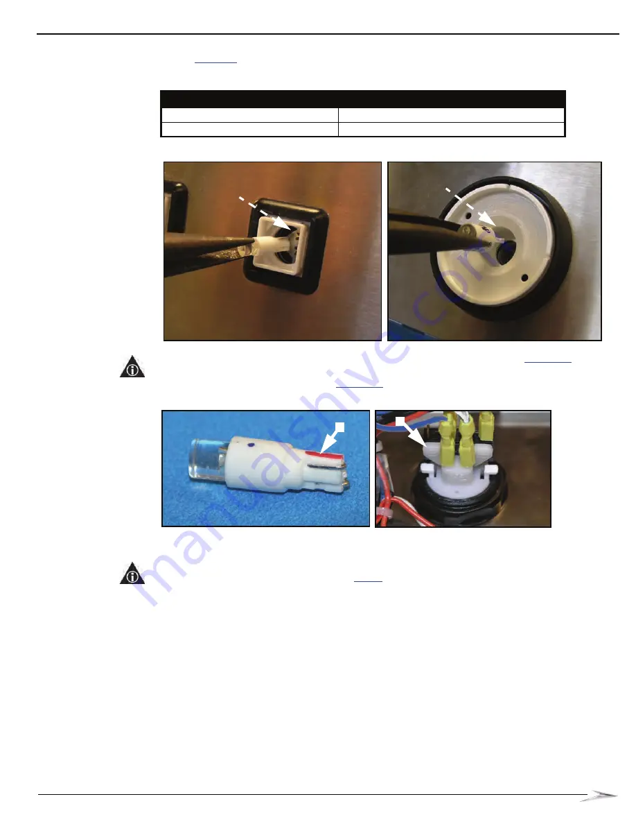
Using the needle-nose pliers, insert the LED into the button socket by determining the following
in
:
Figure 3-5 Inserting the LED into the small button (left) and large button (right).
NOTE:
The smaller LED (24-018185-00-00) is polarity marked with a red stripe
(A). Algin
the stripe with the positive side of the button light socket. The positive side is marked at the cable
connections on the rear of the button,
(B).
Figure 3-6 Polarity stripe on LED (left) and positive marking on rear of button (right).
4
Turn on the game and perform a diagnostic check to confirm that the LEDs light.
NOTE:
If the LED does not light, power OFF the game, remove the LED, rotate the LED, and
reinsert with the opposite polarity. Repeat
step 4
.
Table 3-2 Bulb size.
If the button is a...
then...
small square unit
use LED 24-018185-00-00
.
large circular unit
use LED 24-018186-00-00
.
A
B
Summary of Contents for Bluebird Series
Page 2: ......
Page 12: ...4 List of Figures November 2007 ...
Page 16: ...4 About this Guide General Information October 2007 ...
Page 101: ...5 13 Chapter 5 Exploded Views Block Diagram for BBU AC Power Distribution ...
Page 102: ...5 14 Chapter 5 Exploded Views Block Diagram for BBU Bulkhead with CPU NXT ...
Page 103: ...5 15 Chapter 5 Exploded Views Block Diagram for BBU Bulkhead with CPU NXT ...
Page 104: ......


