background image

Gearless Lift Machine

WSG-W8
Operating Instructions

Seite/page

23

Datum/date

29.01.2010

Stand/version

0.13

Änderungen vorbehalten!

Subject to changes without notice! 

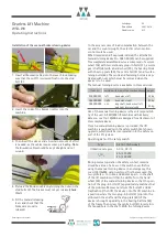
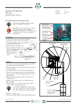
now self-supported on the shaft, proceed to the accurate
positioning and securing of the stop plate. To this end,
screw in the two M16x35 hexagon head bolts (42) and
tighten the centre bolt (41) alternately.

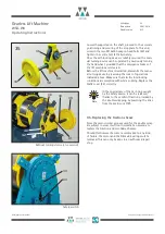
Once the self-locking device is reliably secured, the man-
ual turning device can be operated by cautiously turning
the hand wheel, provided that the emergency brakes of
the lift machine are released.

Before the lift machine is restarted, dismantle the manu-
al turning device by reversing the order of operations
indicated above. Make sure that electric interlocking
conditions are complied with while so doing. Replace the
blank cover (34) correctly. 

9.5. Replacing the traction sheave

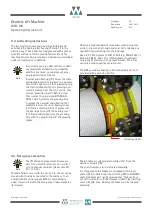
Since the semi-circular grooves used for the double wrap
are subject to wear, it will not normally be necessary to
replace the traction and secondary sheaves.

Should this however become necessary due to any kind
of failure, the motor and the DE main bearing must be
removed. This can only be done in an authorised repair
shop. 

In the special case of the car being caught
by the safety device, it can be released,
thanks to the excellent traction provided by
the double wrapping, by powering the drive
from the mains or a UPS. 

Note

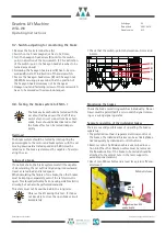
Manual turning device (r.h.s. version)

34

43

37

35

36

39

38

40

42

38

39

36

41

42

40

Safety switch

Summary of Contents for WSG-W8 Series

Page 1: ...whether in part or in full requires the prior written permission of WITTUR Holding GmbH Wittur Holding GmbH reserves the right to make changes in the information and pictures contained in these operat...

Page 2: ...e the contents of this manual and these product details without prior notice We expressly reserve the right to make technical changes which improve the lift machines or their safety stan dards without...

Page 3: ...8 Commissioning 18 9 Operation and maintenance 19 9 1 General 19 9 2 Maintenance intervals 19 9 3 Lubricating instructions 20 9 4 Emergency evacuation 20 9 5 Replacing the traction sheave 23 9 6 Repla...

Page 4: ...ne or more of the following causes Improper use of the WSG W8 lift machine Improper installation commissioning operation or maintenance Operation of the WSG W8 with defective and or inop erative safet...

Page 5: ...re to be operated via an electronic frequency converter Direct connection to the mains may destroy the motor High surface temperatures may occur on the external parts of the machine There fore no temp...

Page 6: ...e of the machine behind the NDE ball bearing 11 It is connected using a plug connector 15 Different types of measuring systems can be offered The motor is electrically connected in the terminal box 16...

Page 7: ...11 NDE bearing 12 Main bearing head external 13 Bearing cover outer 14 Measuring system ECN1313 shown 15 Measuring system signal plug connector 16 Motor terminal box 17 External multiple pole clasp b...

Page 8: ...ch reduce the service life of the ropes An adjustment for this offset must also be made within the overall arrangement This can be achieved by provid ing for a corresponding offset of the counterweigh...

Page 9: ...only in closed dry dust free well ven tilated and vibration free rooms storage temperature 20 C to 60 C Do not store lift machines in the open air Bright parts are not sufficiently preserved to withs...

Page 10: ...moisture con densation Install the machine so that ventilation is not obstructed i e sufficient heat dissipation by convection and radia tion must be ensured The torque and power values indicated in...

Page 11: ...Gearless Lift Machine WSG W8 Operating Instructions Seite page 11 Datum date 29 01 2010 Stand version 0 13 nderungen vorbehalten Subject to changes without notice...

Page 12: ...rgy recovery unit The maximum permissible rate of voltage rise dU dt at the motor terminals may be max 4 kV ms The overvoltage at the motor terminals must not exceed 1 3 kV It may be neces sary to use...

Page 13: ...e of 40 C Handling the terminal strip Cable cross section Permissible max current r m s value Permissible max motor current IN S3 40 1 0 mm2 13 1A 20 7A 1 5 mm2 15 7A 24 8A 2 5 mm2 22 6A 35 7A 4 0 mm2...

Page 14: ...the motor frame for the connection of a protective or earth ing conductor as specified in VDE 0100 and VDE 0141 respectively When using shielded power cables make sure the cable shield metal contacts...

Page 15: ...to the associated con verter Do not change the adjustment as this may make it impossible to use the motor On the measuring system housing there is a label showing the offset angle deter mined at the f...

Page 16: ...breakdown emergency stop or during an inspection drive the switching should be performed from the d c side since this ensures a faster braking effect with the car being stopped earlier It is therefor...

Page 17: ...partial brake zur 3 Teilbremse to the 3 rd partial brake K1 1 Teilbremse 1 st Partial brake Bremsmagnet Brake magnet NC NO C L ften release zur Steuerung to control cabinet Brems berwachung Brake mon...

Page 18: ...eck that the brakes are properly connected and that the brake monitoring switches are functioning properly Is the measuring system properly connected Check that the offset value indicated on the measu...

Page 19: ...rength class and the tight ening torques are observed see table Secure the bolts screws with omnifit 100 or a similar product against accidental loosening 9 2 Maintenance intervals Check the thickness...

Page 20: ...firmly and snugly close the greasing hole with the plug and park the greasing nipple Note Greasing nipple Observe a high standard of cleanliness when doing this work to prevent any foreign material d...

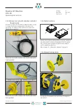
Page 21: ...1 H2b handbet tigt hand operated H2a fu bet tigt foot operated 654 403 377 97 140 352 139 2 x 13 5 The brake lever plates and the asso ciated counter plates also have holes and slots to which Bowden c...

Page 22: ...ice in an emergency this cover 34 4xM6 wing nuts must first be removed The two pinholes 15 in dia and 60 mm apart in the shaft of the lift machine will then be visible Turn the hand wheel 39 of the ma...

Page 23: ...evice by reversing the order of operations indicated above Make sure that electric interlocking conditions are complied with while so doing Replace the blank cover 34 correctly 9 5 Replacing the tract...

Page 24: ...ghten them with a torque spanner using a torque of MA 115Nm Remove the M6 x 65 release screws Insert the M6x40 spring bolts Release the brake electrically and adjust the brake air gap by means of the...

Page 25: ...nitoring the brakes Check the brake monitoring switches individually No car travel must be permitted if a micro switch signal is miss ing or a wrong signal operates Separate operation of the individua...

Page 26: ...n the stud and the measuring system shaft end do not grease them Remove the cable cover from the measuring system Plug in the measuring system insert the M5x50 faste ning screw in the hollow shaft and...

Page 27: ...locked Overexcitation rectifier defective Check electrical connection Check braking voltage supply voltage Remove mechanical blocking Replace overexcitation rectifier Delay in braking system release O...

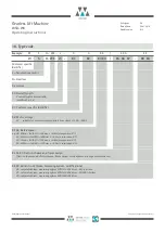
Page 28: ...onverter supply using a link voltage of 500 620V X3 X4 Rated speed e g 06 60min 1 with DT 400mm v 0 6m s suspension 2 1 24 240min 1 with DT 400mm v 2 5m s suspension 2 1 07 75min 1 with DT 320mm v 0 6...

Page 29: ...protection triple PTC 150 C Site conditions Max altitude max 1 000 m derating required at higher altitudes Ambient temperature 5 C 40 C Max rel humidity 85 at 20 C no moisture cendensation caliper dis...

Page 30: ...8 5 75 8 6 28 5 60 6 9 28 5 1 0 119 9 2 26 9 95 7 4 18 5 119 13 7 43 0 95 10 9 28 5 1 6 191 14 8 41 3 153 11 9 26 9 191 22 0 62 5 153 17 6 43 0 2 0 239 18 5 41 3 190 14 7 41 3 239 27 5 62 5 190 21 9 6...

Page 31: ...plete with secondary sheave Frame motor with secondary sheave additionally approx 15kg per 100 mm centre distance AH for secondary sheave bracket and approx 5 6 kg per foot Execution examples Typschl...

Page 32: ...165 7 5 4 05 400 400 185 13 13x13 169 8 5 05 The WSG W8 lift machine comprises a com pact frame motor an adaptable secondary sheave block and optional feet The secondary sheave block can be fitted off...

Page 33: ...313 EnDat or SSI 502 452 021 xx emotron Dietz DSV 5445 ECN1313 EnDat or SSI 501 112 022 xx Flender Loher L05 ERN 1387 507 874 022 xx Fuji Frenic ECN1313 EnDat 502 679 022 xx KEB F5 ECN1313 EnDat 502 3...

Page 34: ...g e x x i s o l i e r t e A d e r e n d h l s e n 1 5 m m 2 S A D A r t N r 3 6 6 1 1 1 2 9 1 8 8 1 0 0 1 5 0 1 6 5 K a b e l f r T e m p e r a t u r b e r w a c h u n g x x i s o l i e r t e A d e r...

Page 35: ...Subject to changes without notice 13 4 Rubber cushions Solid borne sound absorbing elements rubber cushions should be used for vibration damping in the lift system The cushions must be dimensioned an...

Page 36: ...ic type lubricating nipple DIN71412 AM 10x1 03 Dummy stopper N Pg9 DIN46320 Fs 04 Rope slip off guard cpl 505648 05 Measuring system depending on spec ECN1313 SSI 2048 incr clamping ring ECN1313 ENDAT...

Page 37: ...Gearless Lift Machine WSG W8 Operating Instructions Seite page 37 Datum date 29 01 2010 Stand version 0 13 15 EC type examination certificate nderungen vorbehalten Subject to changes without notice...

Page 38: ...Gearless Lift Machine WSG W8 Operating Instructions Seite page 38 Datum date 29 01 2010 Stand version 0 13 nderungen vorbehalten Subject to changes without notice...

Page 39: ...Gearless Lift Machine WSG W8 Operating Instructions Seite page 39 Datum date 29 01 2010 Stand version 0 13 nderungen vorbehalten Subject to changes without notice...

Page 40: ...08 x and xSG W8 x Year of Construction see name plate on product and shipping documents Serial number see name plate on product and shipping documents EC type examination ABV 716 4 dated 2007 11 15 is...

Reviews: