


3.2
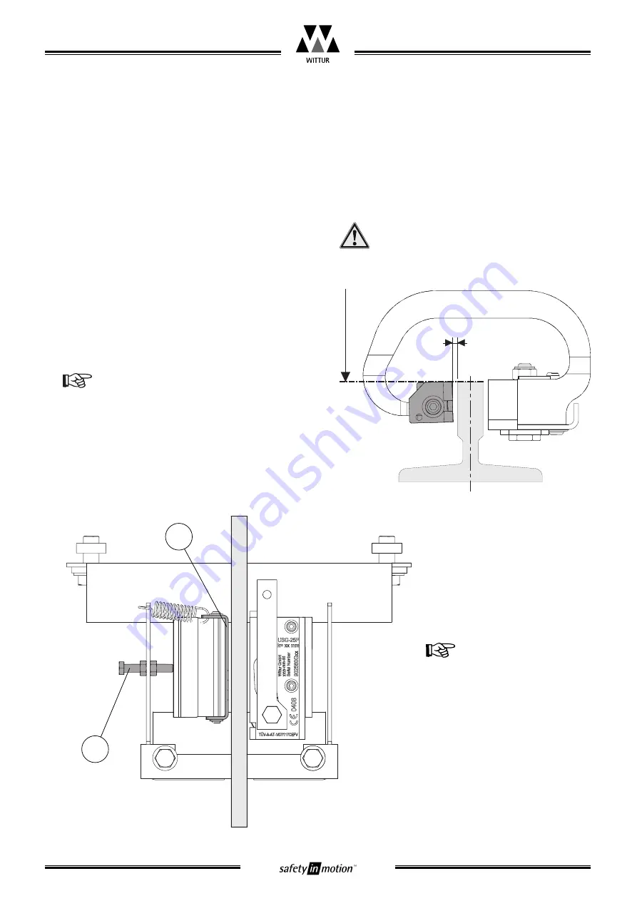
Adjustment of running clearance
(gap brake lining to guide rail)
After mounting and alignment of the safety gear,
adjust the running clearance “A” (see Fig.2).
Adjustment (on sample option housing):
(
1
) Check, if the safety gear can be moved side-
ways easily (move by hand manualy)!
(
2
) Ensure that the gripping roller rests in it’s ini-
tial most bottom position.
Refer also to synchronisation adjustment
(chapter 3.4)
(
3
) Adjust the running clearance of 3,0
+0/-0,5
mm
between brake lining (3) and guide rail by
means of the limiter screw (8)
(
4
) Lock the limiter screw (8) with the counter
nuts
Check the horizontal alignment!
The brake lining edge have to be on the
same level as the guide rail nose edge
(
5
) Repeat this adjustment se-
quence on the other safety
gear
Check the horizontal
movement of the safety
gears - the movement
should be able to be
done easily by hand. Be
sure that brake lining (3)
is able to access the
guide rail when safety
gear is activated.
Blatt/
sheet
D729MGB.011
Datum/
date
23.05.2007
Stand/
version G-07.05.2018
Geprüft/
approved WAT/MZE
Änderungen vorbehalten!
Subject to change without notice!
Progressive Safety Gear
USG-25P
Operating Instructions
DBG
A=3,0mm
+0/-0,5
fig. 2: Running clearance
8
3


