installation & connection
10_
installation & connection
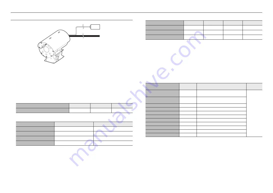
CONNECTING WITH OTHER DEVICE
Ethernet Connection
Connect the Ethernet cable to the local network or to the Internet.
Power Supply
Connect the power supply line with the camera power supply terminal using a screwdriver.
J
`
Be sure to connect the AC24V power supply (non-polar) while the power is shut off.
AC24V power supply wire specification
Wire Type (AWG)
#22
#20
#18
Cable Length (Max.)
34 m
55 m
88 m
Network Cable Specification
Item
Contents
Remark
Connector
RJ45
Ethernet
10/100Base-T
10/100 Mbps
Cable
UTP Category 5e
Max Distance
100 m
Ethernet
External cables
Electrical Resistance of Copper Wire at [20°C (68°F)]
Copper Wire Gauge (AWG)
#24(0.22mm
2
)
#22(0.33mm
2
)
#20(0.52mm
2
)
#18(0.83mm
2
)
Resistance (Ω/m)
0.078
0.050
0.030
0.018
Drop Voltage (V/m)
0.028
0.018
0.011
0.006
Recommended Distance (m)
Less than 20
Less than 30
Less than 30
Less than 30
`
As shown in the table above, you may encounter a voltage-sag depending on the wire length.
If you use an excessively long wire for camera connection, the camera may not work properly.
-
Camera Operating Voltage: AC 24V±10%
-
Voltage drop measurements on the chart above may vary depending on the type and manufacture of the copper cable.
How to connect external cables for each model
Connect external cables by referring the table below.
J
`
Connect alarm input/output cables for each terminals one by one.
Label print
COLOR
Description
Remarks
(Length)
GND / GRN
GREEN
A common terminal to connect external Alarm signal
(GND)
3 m
ALARM COM / BRN
BROWN
A common terminal to connect Alarm output signal
(COM)
ALARM OUT / YEL
YELLOW
A terminal to connect Alarm output signal
ALARM IN / ORG
ORANGE
A terminal to connect external Alarm signal
WAS COM / BLU
BLUE
A common terminal to connect Washer Pump (COM)
WAS NO / PUP
PURPLE
A terminal to connect Washer Pump (NO)
WAS NC / WHT
WHITE
A terminal to connect Washer Pump (NC)
AC 24V_A
RED
A terminal for 24Vac power supply input (A)
AC 24V_B
BLACK
A terminal for 24Vac power supply input (B)
MIC IN
RED
Microphone input port
SPK-OUT
YELLOW
Speaker output port
Summary of Contents for TNO-6322ER
Page 1: ...NETWORK CAMERA User Manual TNO 6322ER ...
Page 21: ......


