background image

English_37


C

amer

a

 Oper

a

ti

O

n


y

MOTION : 


This product generates signals each time an object movement is detected in the four areas 
of the screen so efficient monitoring can be achieved.


  If the SPECIAL menu screen is displayed, use the Function Setup switch so that the arrow 
indicates ‘MOTION’.

  Select a desired mode using the 
Function Setup switch.


y

DET. AREA :  Set the areas of 

motion detection.


`

SEL AREA :  Select from four areas 

that users want.


`

MODE :  Determine whether to use the selected area.


`

MASK :  Under Motion Detection, If you don’t want to see mosaic image on the 

screen, you may turn MASK OFF. 
If you wants to see mosaic image, please turn it on.


`

TRANSPARENCY:   Adds or removes transparency from the masking area.


`

TOP/BOTTOM/LEFT/RIGHT :  Area location can be adjusted.


`

RETURN :  Return to the MOTION DET menu.


y

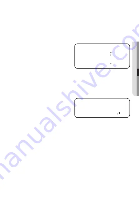
ALARM OUT :  When object 

movement is 
detected, the 
detection signal 
will be outputted.


`

EXTERNAL :  Send signals through external terminals.


`

OSD : Display signals on the screen.


`

RETURN : Return to the MOTION DET menu.


y

SENSITIVITY :  Set the sensitivity of the motion detection. When you adjust the 

higher level, the more sensitive.


y

RETURN :  Return to the SPECIAL SETUP menu.


M


`

Depending on the shape of an object, there can be errors in size detection.


`

If the camera shoots an object a short distance away, the motion detection function can 
be degraded.


`

In the following cases, motion detection event performance can be degraded or 
malfunctions can occur.
- If an object’s brightness or color is similar to that of the background

MOTION DET

 1. 

DET. AREA 


 2. 

ALARM OuT 


 3. 

SENSITIVITY


IIIIIIIIII

I

IIIIIIIIII


5

  4. 

RETuRN 


ALARM OuT

 1. 

EXTERNAL 

ON

 2. 

OSD 

ON

 3. 

RETuRN


Summary of Contents for HCD-6070R

Page 1: ...High Resolution Camera User Manual HCD 6070R HCV 6070R ...

Page 2: ...d Undernocircumstances thisdocumentshallbereproduced distributedorchanged partiallyorwholly withoutformalauthorization Disclaimer Hanwha Techwin makesthebesttoverifytheintegrityandcorrectnessofthecontentsinthisdocument butno formal guaranteeshallbeprovided Useofthisdocumentandthesubsequentresultsshallbeentirelyontheuser sownresponsi bility Hanwha Techwin reservestherighttochangethecontentsofthisdo...

Page 3: ... power voltage To help you understand this manual thoroughly we ll introduce our model description HCD 6070R HCV 6070R SERIES NTSC MODEL PAL MODEL HCD 6070R HCD 6070RP HCV 6070R HCV 6070RP MODEL DESCRIPTION HCX 6070RX _ SIGNAL SYSTEM N NTSC MODEL P PAL MODEL SIGNAL SYSTEM ...

Page 4: ...zard do not expose this appliance to rain or moisture To prevent injury this apparatus must be securely attached to the floor wall in accordance with the installation instructions WARNING 1 Be sure to use only the standard adapter that is specified in the specification sheet Using any other adapter could cause fire electrical shock or damage to the product 2 Incorrectly connecting the power supply...

Page 5: ...ock CAUTION 1 Do not drop objects on the product or apply strong shock to it Keep away from a location subject to excessive vibrationor magnetic interference 2 Do not install in a location subject to high temperature over 55 C low temperature below 10 C or high humidity Doing so may cause fire or electric shock 3 If you want to relocate the already installed product be sure to turn off the power a...

Page 6: ... be disposed of with other household waste at the end of their working life Where marked the chemical symbols Hg Cd or Pb indicate that the battery contains mercury cadmium or lead above the reference levels in EC Directive 2006 66 If batteries are not properly disposed of these substances can cause harm to human health or the environment To protect natural resources and to promote material reuse ...

Page 7: ...n or pinched particularly at plugs convenience receptacles and the point where they exit from the apparatus 11 Only use attachments accessories specified by the manufacturer 12 Use only with cart stand tripod bracket or table specified by the manufacturer or sold with the apparatus 13 Unplug this apparatus when a card is used Use caution when moving the cart apparatus combination to avoid injury f...

Page 8: ...e product in a manner that has not been recommended the production functions performance may not be guaranteed Install the product by referring to Installation connection in the user manual 20 Installing or using the product in water can cause serious damage to the product Apparatus shall not be exposed to dripping or splashing and no objects filled with liquids such as vases shall be placed on th...

Page 9: ... 15 15 Before installation 15 Installation 20 Adjusting the monitoring direction for the camera connection 22 22 Connecting to Monitor 23 Connecting to Power 24 Using Coaxial Communications camera operation 26 26 Menu Configuration 26 Menu Setup troubleshooting 39 39 Troubleshooting specifications 40 40 Specifications 42 Dimension ...

Page 10: ...ht time conditions to enhance the definition of the image y y PROFILE You can set a mode according to the camera installation conditions BASIC DAYNIGHT BACKLIGHT ITS INDOOR USER y y WDR By adopting a proprietary high performance DSP chip the camera delivers clear high quality pictures even in backlight by increasing exposure in dark areas while decreasing it in bright areas a corrected image with ...

Page 11: ...English_11 introduction Components and Accessories Check if the following items are included in the product package HCD 6070R Camera QuickManual Screws Template VideoOutputCable ...

Page 12: ...12_ introduction introduction HCV 6070R TO P FR ON T Camera QuickManual Template TappingScrew MachineScrews LWrench Card typemoisture absorbent VideoOutputCable ...

Page 13: ...AHD and CVBS modes Press the SET button for more than 5 seconds 6 Video OutputTerminal to Monitor 7 Pan Base Control panning angle of camera 8 Power Input Connector 9 GroundTerminal MD OutputTerminal Motion detection signals are output through this terminal Video Output Jack Video signals are output through this port Connect this port to theVideo IN port of a AHD DVR IR LED These infrared LED s ar...

Page 14: ...e SET button for more than 5 seconds 5 Video OutputTerminal to Monitor 6 Pan Base Control panning angle of camera 7 Power Input Connector 8 GroundTerminal 9 MD OutputTerminal Motion detection signals are output through this terminal Video Output Jack Video signals are output through this port Connect this port to theVideo IN port of a AHD DVR IR LED These infrared LED s are controlled by the illum...

Page 15: ... the electric line cover to be damaged Otherwise it may cause a breakdown or fire y y Before installing your camera you have to adjust the lens focus zoom and switch settings y y When installing your camera don t allow any person to approach the installation site INSTALLATION Disassembling HCD 6070R 1 Use one hand to hold the camera s bottom part and turn the cover counterclockwise with another ha...

Page 16: ...Installation 16_Installation Disassembling HCV 6070R Using the L wrench provided loosen 3 screws by turning them counterclockwise and separate the dome cover T O P F R O N T Dome Cover LWrench ...

Page 17: ...s to fi x the camera to the 2 punched holes y y Set the TOP FRONT mark imprinted on the camera to face the direction of camera monitoring 3 Adjust the lens in a desired direction by referring to the Adjusting the monitoring direction for the camera section 4 Attach the dome cover and the shield case to the main body M M Pay attention to the direction for assembly 케이블 구멍 ...

Page 18: ...chors HUD 5 not included fully into the holes Fix the case bed on the ceiling by using screws 3 places 2 Connect Power and video cables and arrange them through the hole you want to pass when mounting the main body on the mounting bracket note that not to damage or squeeze the cables T O P F R O N T screw T O P F R O N T Video output jack Function jack Power input terminal ...

Page 19: ... Close the dome cover To ensure waterproofing tight up the fixing bolts using the L wrench T O P F R O N T Dome Cover LWrench M M The installation should be done by qualified service personnel or system installers If the ceiling material is not strong enough to hold the installation screws the camera may fall off Reinforce the ceiling as needed ...

Page 20: ...Installation 20_Installation Adjustingthe monitoring direction forthe camera Pan Tilt Lens rotation T O P F R O N T Pan Tilt Lens rotation HCD 6070R HCV 6070R ...

Page 21: ...n is a total of 350 degrees The effective range of rotation is a total of 355 degrees The effective range of tilt is a total of 67 degrees Methods of adjustment 1 After installing the camera adjust the panning angle in consideration of the monitoring direction 2 Adjust the view angle and focus for the video For convenience of operation adjust the rotation part to fix the lever 3 Set the horizontal...

Page 22: ...efer to the manual supplied with the instrument y y Only connect the cable when the power is turned off M M This product supports 4 video output formats of AHD CVBS TVI and CVI The default is AHD Select the video output appropriate for your DVR REC HDD ALARM NETWORK BACKUP POWER REC HDD ALARM NETWORK BACKUP POWER TO P FR ON T HCD 6070R HCV 6070R AHD DVR AHD DVR Monitor Monitor ...

Page 23: ...ng figure When the resistance value of copper wire is at 20 C 68 F Copperwiresize AWG 24 0 22mm2 22 0 33mm2 20 0 52mm2 18 0 83mm2 Resistancevalue Ω m 0 078 0 050 0 030 0 018 VoltageDrop V m 0 028 0 018 0 011 0 006 TO P FR O N T Power Input Terminal HCD 6070R HCV 6070R Power Input Terminal ...

Page 24: ...a Standard voltage for camera operation DC 12V 10 AC 24V 10 There may be some deviation in voltage drop depending on the type of wire and the manufacturer M M Be sure to connect power only after all the installation is complete Using Coaxial Communications y y Coaxial Communications System y y OSD Control method CAMERA DVR SET MENU ENTER UP UPKEY DOWN DOWNKEY LEFT LEFTKEY RIGHT RIGHTKEY TO P FR ON...

Page 25: ...nd not copper coated steel as this will cause issues with the communication over the coaxial cable To ensure picture quality only single channel video output connector can be used while camera connected to other video equipments Video Cable The camera s video output port is connected to the DVR with a BNC coaxial cable shown below ...

Page 26: ...DOOR OUTDOOR MANUAL AWC SET EXPOSURE BRIGHTNESS LENS SHUTTER AGC SSNR4 SSDR RETURN BACKLIGHT OFF USERBLC HLC WDR SPECIAL DISPLAY COAX IMAGEADJ DAY NIGHT DEFOG PRIVACY MOTION RETURN EXIT SAVE NOTSAVE RESET Menu Setup For function setting you can use the function setting switch inside the dome cover camera operation Function Setup switch HCD 6070R ...

Page 27: ...DEO FORMAT 1 When the SETUP menu screen is displayed select VIDEO FORMAT by using the Function Setup switch so that the arrow indicates VIDEO FORMAT 2 Select a desired mode using the Function Setup switch y y The video output can be selected from AHD CVBS CVI TVI M M By pressing the function setting button for more than 5 seconds you can change the setting from AHD TVI and CVI to CVBS From CVBS yo...

Page 28: ... to help you take a picture in a regular indoor lighting condition y y USER Automatically configures the camera to your custom settings 1 Select Custom for Simple Setup mode 2 Configure the menu options to your custom settings 3 The settings are automatically saved as Custom mode 4 Profile user mode don t initialize when menu resets 3 In the PROFILE menu you can confi gure the following camera set...

Page 29: ...UAL Selectthistofine tuneWhite Balancemanually SetWhite BalancefirstbyusingtheATW orAWCmode Afterthatbutton toMANUALmode fine tunethe WhiteBalanceandtheFunction Setupswitch y y AWC SET Tofindtheoptimalluminancelevelforthecurrentenvironment pointthe cameratowardsasheetofwhitepaperandpresstheFunctionSetupswitch Ifthe environmentchanges readjustit M M White Balance may not work properly under the fol...

Page 30: ...cally move but is fixed to the maximal degree in this mode M M Some lenses may not work properly depending on the setting of the BRIGHTNESS LEVEL y y SHUTTER Youcanselecttheshutter MIN 1 1 12000 MAX 1 60 1 12000 NTSC 1 50 1 12000 PAL A FLK Select this when you experience picture flicker this happen when there is a clash with the installed lighting frequency M M The greater the shutter value the br...

Page 31: ...e Function Setup switch to change the SSDR level in the sub menu according to the contrast between bright and dark areas OFF Turn off SSDR function BACKLIGHT The camera uses high performance DSP chips that are designed to clearly display the object and the background despite severe reverse light 1 When the SETUP menu screen is displayed select BACKLIGHT by using the Function Setup switch so that t...

Page 32: ...N Return to the MAIN SETUP menu M M If the white balance menu is set to manual then HLC performance can be limited If you use the defog and HLC functions at the same time saturation can occur in a bright environment Because there can be a difference in the effectiveness of HLC according to the amount of light area in the screen optimize the installation angle for the best HLC performance When dark...

Page 33: ...press the Function Setup switch The entered title appears on the screen Select the position to display the title on the screen by using the Function Setup switch and press the Function Setup switch When the position is determined select END and press the Function Setup switch to return to the DISPLAY menu M M When the CAMTITLE menu is OFF no title will be displayed on the monitor screen even if yo...

Page 34: ...setting is the higher the PED level gets COLOR GAIN The setting range is 1 100 The smaller the setting value is the smaller the color gain gets and the more color blind it gets H REV Flip an image horizontally V REV Flip an image vertically SHARPNESS Select a mode to adjust the thickness of an image s sharpness Increase or decrease the level of each mode to adjust the level of sharpness y y OFF Re...

Page 35: ...lect the brightness of light where switching occurs y y DWELL TIME You can select day night switching delay time from 3s 5s 7s 10s 15s 20s 30s 40s 60s M M If you set the AGC mode to off on the exposure menu you cannot switch the day night mode to auto When a bright light source is in the screen or there are frequent brightness changes if you use the auto night day mode and set the switching time t...

Page 36: ... Manual If there is little fog and the manual fog level is high the screen contrast can get high y y PRIVACY Maskanareayouwanttohideonthescreen If the SPECIAL menu screen is displayed use the Function Setup switch so that the arrow indicates PRIVACY Select a desired mode using the Function Setup switch AREA You can select up to 8 PRIVACY areas MODE Determines whether to use the area selected in th...

Page 37: ...HT Area location can be adjusted RETURN Return to the MOTION DET menu y y ALARM OUT When object movement is detected the detection signal will be outputted EXTERNAL Send signals through external terminals OSD Display signals on the screen RETURN Return to the MOTION DET menu y y SENSITIVITY Set the sensitivity of the motion detection When you adjust the higher level the more sensitive y y RETURN R...

Page 38: ... light such as direct sunlight lights and headlights Severe snow rain and wind Sunset or sunrise If the size is greater than the max size or smaller than the min size motion is not detected To avoid false detection caused by noises set the max min detection size suitable for the installation environment But the same movement in the same location can cause a different detection size So include marg...

Page 39: ...ined with dirt Clean your lens with soft clean cloth y y Set the monitor or DVR to the proper condition y y If the camera is exposed to very strong light change the camera position The image on the screen is dark y y Adjust the contrast feature of the monitor or DVR y y If you have an intermediate device set the 75Ω Hi z properly The camera is not working properly and the surface of the camera is ...

Page 40: ...Lens Type Focal Length Zoom Ratio 3 2 10mm 3 1x varifocal Max Aperture Ratio F1 6 Angular Field of View H 110 2 Wide 32 Tele V 55 4 Wide 18 Tele D 128 4 Wide 36 6 Tele Min Object Distance 0 5m 1 64ft Focus Control Manual Lens Type DC Auto Iris Mount Type Board in type Operational On Screen Display Multi language Support 16 English Japanese Spanish French Portuguese Korean German Italian Russian Po...

Page 41: ...ocol CVBS Pelco C Coaxitron CCP CVI Coax Protocol TCP TVI Coax Protocol IR Distance 20m 65 62ft 30m 98 43ft Video Transmission Distance 500m 5C2V Environmental Operating Temperature Humidity 10 C 55 C 14 F 131 F Less than 90 RH 30 C 55 C 22 F 131 F Less than 90 RH Start up should be done at above 10 C Ingress Protection IP66 Vandal Resistance IK10 Electrical Input Voltage Dual 24VAC 10 12VDC 10 Po...

Page 42: ...42_ specifications Dimension Unit mm inch HCD 6070R ...

Page 43: ...English_43 specifications Unit mm inch HCV 6070R ...

Page 44: ...www hanwha security com Hanwha Techwin America 500 Frank W Burr Blvd Suite 43 Teaneck NJ 07666 Toll Free 1 877 213 1222 Direct 1 201 325 6920 Fax 1 201 373 0124 www hanwha security com Hanwha Techwin Europe Heriot House Heriot Road Chertsey Surrey KT16 9DT United Kingdom Tel 44 1932 57 8100 Fax 44 1932 57 8101 www hanwha security eu ...

Reviews: