installation & connection
28_
installation & connection
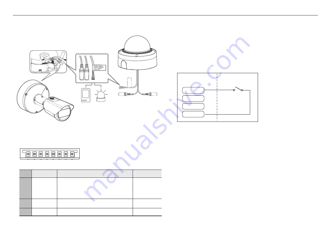
Connecting to the I/O port box
Connect the Alarm I/O cable to the corresponding port of the port box.
Sensor
Alarm
(Warning lamp)
Alarm-related Connector
J
`
Make sure to connect the provided audio/alarm cable before use.
1
2 3
4 5
6 7 8
NO
Function
Description
Color
6, 7
ALARM I/O 1,
ALARM I/O 2
These ports can be used as alarm input or output ports. If used
as input ports, alarm input or day/night sensors can be connect to
them. If used as output ports, alarm output signals can be connect
to them.
※
Alarm I/O changes can be made through the Webviewer setup.
BROWN : ALARM I/O 1
ORANGE : ALARM I/O 2
8
DC 12V/50mA
This is the power connector. (DC 12V/50mA)
RED
5
GND
Common port for alarm in/output signal.
BLACK
J
`
If devices (e.g., flashing light and siren) that exceed the voltage and current specifications are connected by using the open
collector method, it may cause malfunction.
Refer to the “
Alarm Out Wiring Diagram
” when connecting devices that exceed the voltage and current specifications. (page 29)
To connect the external sensor
Connect one of the 2 signal lines to the [ALARM I/O 1] port (if you want this to be the input port) and the
remaining one to the [GND] port.
Alarm In Wiring Diagram(example)
Sensor
External connection
ALARM I/O 1
ALARM I/O 2
DC 12V/50mA
GND
Alarm cable
<If ALARM I/O 1 is set as an input terminal>


