Limited Lifetime Warranty
This Wirepath Product has a Lifetime Limited Warranty. This warranty includes parts and labor repairs on all components found to be defective in
material or workmanship under normal conditions of use. This warranty shall not apply to products that have been abused, modified, or disassembled.
Products to be repaired under this warranty must be returned to SnapAV or a designated service center with prior notification and an assigned return
authorization number (RA).
Lifetime
Rev:
200908
-
0843
www.snapav.com Support: 800.838.5052
Hinged Doors
Flush Mount Doors
Dimensions
WP-DOOR-HINGE-14 — 15.35”W x 15.12”H x 0.25”D
WP-DOOR-HINGE-20 — 15.35”W x 21.1”H x 0.25”D
WP-DOOR-HINGE-28 — 15.35”W x 29.1”H x 0.25”D
WP-DOOR-HINGE-40 — 15.35”W x 41.10”H x 0.25”D
WP-DOOR-FLUSH-14 — 15.35”W x 15.12”H x 0.25”D
WP-DOOR-FLUSH-20 — 15.35”W x 21.1”H x 0.25”D
WP-DOOR-FLUSH-28 — 15.35”W x 29.1”H x 0.25”D
WP-DOOR-FLUSH-40 — 15.35”W x 41.10”H x 0.25”D
Installation Screws WP-DOOR-HINGE-14 — 4 screws
WP-DOOR-HINGE-20 — 4 screws
WP-DOOR-HINGE-28 — 8 screws
WP-DOOR-HINGE-40 — 8 screws
WP-DOOR-FLUSH-14 — 4 screws
WP-DOOR-FLUSH-20 — 4 screws
WP-DOOR-FLUSH-28 — 4 screws
WP-DOOR-FLUSH-40 — 4 screws
Keys
Yes (2)
N/A
UL Certified
Yes
Yes
Steel Gauge
20
20
Color
White Powder Coat Finish
White Powder Coat Finish
Dual Locking
Yes
N/A
Doors
A
C
B
B
H
!
!
WARNING: ELECTRICAL SHOCK HAZARD!
Cutting or drilling into
electrical wires or cables can cause death or serious personal injury!
ALWAYS make certain the area behind mounting surfaces is free of
electrical wires and cables before cutting, drilling, or installing fasteners.
DANGER: IMPROPER WIRING CAN LEAD TO DEATH OR SEVERE
PERSONAL INJURY!
Grounding must be installed by qualified personnel
using a UL Recognized No. 12 AWG Green and Yellow grounding wire
connected to the grounding lug on the enclosure. Proper grounding of the
unit should be verified by a
q
u
a
lified electrician and compliant with the
National Electrical Code.
Newer Installation Instructions
In a new installation (Figure 1), position the enclosure at the de
-
sired location, level between the studs, and flush with the front of
the studs. Drive a minimum of 2 screws in each side of the enclo
-
sure, and into the sides of the studs.
Older Installation Instructions
In an older installation (Figure 2) with drywall installed, trace the
back of the enclosure at the desired location, level between the
studs. Afterward, recess the box into the hole, keeping it flush with
the front of the drywall. Drive a minimum of 2 screws in each side
of the enclosure, and into the sides of the studs.
Surface Installation Instructions
When mounting to a typical 3/4” plywood backboard (Figure 3),
locate the desired position, and leave rear conduit entries (B)
clear for running wire, if necessary. It may be easier to “rough-in”
your wiring through the backboard prior to full installation. Ensure
the enclosure is level, and drive a minimum of 4 (14”, 20”), or 6
screws (28”, 40”) into the enclosure through the Surface Mount
Holes (H), and/or through the module attachment holes.
Grounding Procedure
Attach a UL listed, closed loop connector with a minimum 12
AWG wire to the included M5 grounding screw and washer. En
-
sure that it is tightly fastened so the washer will penetrate the
powder coating.
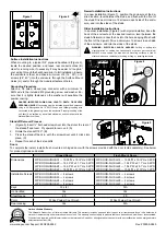
Figure 1
Figure 2
Figure 3
Figure 5
1. (Figure 5) Insert ¼” flat head screwdriver into the slot at the rear of
the standoff and twist. Pry upward to remove it. (A)
2. Rotate the standoff 180°. (B)
3. Press the standoff back in with the screwdriver until it clicks into
place. (C)
4. Repeat for each of the 4 standoffs.
Standoff Removal Process
To complete the install, install a flush mounted or hinged door with the screws provided with the door (sold separately). See below
for product options and details.
Figure 4


