


140721
PRODUCT
MANUAL
PCM-MIO-G-1 17
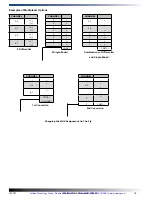
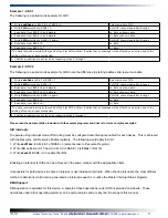
Example 1 - ADC1
The following is a polled mode example for A/D1.
1. Write
xxx00xxx
to bits 3 & 4 of BASE +3.
Select access to CMD
2. Write
CMD
selection to BASE +2.
Set MUX channel operation & range
3. Read data from BASE +0 and discard.
Lo_Byte unknown data
4. Read data from BASE +1 and discard.
Hi_Byte unknown data
5. Write
CMD
selection to BASE +2 again.
Set MUX channel operation & range
6. Read data from BASE +0.
Lo_Byte
7. Read data from BASE +1.*
Hi_Byte
*The data received is actually the result of the first CMD written. Realize that all readings will be offset by one action due to the
latching of the serial input mechanism.
8. Additional readings are achieved by repeating steps 5 through 7.
Example 2 - ADC2
The following is a polled mode example for A/D2, note the difference in starting address and resource enable.
1. Write
xxxx0xxx
to bit 3 of BASE +7.
Select access to CMD
2. Write
CMD
selection to BASE +6.
Set MUX channel operation & range
3. Read data from BASE +4 and discard.
Lo_Byte unknown data
4. Read data from BASE +5 and discard.
Hi_Byte unknown data
5. Write
CMD
selection to BASE +6 again.
Set MUX channel operation & range
6. Read data from BASE +4.
Lo_Byte
7. Read data from BASE +5.*
Hi_Byte
*The data received is actually the result of the first CMD written. Realize that all readings will be offset by one action due to the
latching of the serial input mechanism.
8. Additional readings are achieved by repeating steps 5 through 7.
Please read the documentation included with the sample programs and drivers for more complex examples.
A/D Interrupts
To operate using interrupt mode, IRQ routing must be configured and interrupts enabled for each device. This is achieved
with the Resource and Resource Enable registers. The following would apply to A/D1:
1. Write
xxx01xxx
to bits 4 & 3 of BASE +3 (select access to Resource Register).
2. Write IRQ selection (0-15 hex) to bits 3-0 of BASE +2 (
xF Hex
= IRQ 15).
3. Write
xxxxxx1
BASE +3 to enable the IRQ.
Enabling an interrupt for A/D2 can be achieved in the same manner with the appropriate offset.
It is possible for both devices to share an interupt or use individual interrupts. When sharing interrupts, the most efficient
method to determine which device generated an interrupt request is to utilize the Master Interrupt Status Register.
DMA Support
DMA operation is available for this device. A sample of these operations under DOS is provided on website. These
operations under other operating systems can be quite complex and are beyond the scope of this manual.
Artisan Technology Group - Quality Instrumentation ... Guaranteed | (888) 88-SOURCE | www.artisantg.com