Winners Only GK Aassembly Instructions Download Page 4

Chart 5

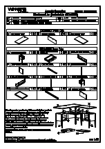
Step 9. Using a Mallet, carefully insert the wood dowels (6PCS) in R1B pedestal (A), RSF

            side panel (F) and R2B pedestal (L).

Step 10. Loosen the screws to adjust metal figure 8 (23PCS) of its direction of the panel and

              re-screw .

Chart 6 Once the R1 desk top (B) and R2 desk top (K) are aligned.

Step 11. Insert short (3/4") flat head wood screws (23PCS) through metal figure 8 to

              connect R1 desk top (B),R2 desk top (K) and base.

Step 12. Use long (1-1/4") flat head wood screws (2PCS) to connect cross bar (G) to

             R1 desk top (B), and cross bar (N) to R2 desk top (K).

11

9

10

11

X1

N

X10

12

K

11

9

9

10

10

10

10

10

10

10

10

10

10

10

10

10

10

10

10

10

10

10

10

10

10

9

9

X1

12

11

X13

11

11 11

11

11

11

11

11

11

11

11

11

11

11 11

11

11

11

11

11

11

9

9

Summary of Contents for GK

Page 1: ......

Page 2: ... side panel F to corner leg 1 H use 1 1 4 machine bolts 3PCS to connect them Step 3 Use 1 1 4 machine bolts 2PCS to connect RHS glide panel D to back panel E Step 4 Using a Mallet carefully insert center Cross Bar G to R1B pedestal A and RHS glide panel D carefully turn the assembled base straight up Use 1 1 4 flat head wood screws 2PCS to connect Cross Bar G to R1B pedestal A and RHS glide panel ...

Page 3: ...sing a Mallet carefully insert cross bar N to R2B pedestal L and LHS glide panel I carefully turn the assembled base straight up Use 1 1 4 flat head wood screws 2PCS to connect cross bar N to R2B pedestal L and LHS glide panel I Chart 4 Step 8 Assemble the Return Desk to the Main Desk by using 1 1 4 machine bolts 5PCS to connect RSF side panel F to corner leg 2 J and LHS glide panel I to RHS glide...

Page 4: ...d R2 desk top K are aligned Step 11 Insert short 3 4 flat head wood screws 23PCS through metal figure 8 to connect R1 desk top B R2 desk top K and base Step 12 Use long 1 1 4 flat head wood screws 2PCS to connect cross bar G to R1 desk top B and cross bar N to R2 desk top K 11 9 10 11 X1 N X10 12 K 11 9 9 10 10 10 10 10 10 10 10 10 10 10 10 10 10 10 10 10 10 10 10 10 10 9 9 X1 12 11 X13 11 11 11 1...

Page 5: ...top of the Main Desk Step 14 Install the drop front center drawer C and keyboard pullout M to place Important Be sure to move the ball bearing retainer all the way to the front of the glide and carefully slide the rails into the glides and ball bearing retainer Assembly is now complete C M ...

Reviews: