background image


2-2 Starting the Panel PC& O/S Installation 

1.  Connect the power to AC/DC adapter, and connect the power cord to the 

AC outlet. 

2.  Press the power on switch to start the Panel PC. 

3.  Press “DEL” to enter the CMOS setting and check the BIOS setup. 

4.  You may install your own O/S if it is not installed. 

When installing O/S for this Panel PC, please follow the steps and use external 

equipment as 

Keyboard and Mouse.

(a)  Please use external USB DVD-ROM to run the O/S and Driver setting (as 

picture showed below). 


USB Cable 


2-3 Driver Installation 

’s Manual and Driver CD that contains most of the 

stall Driver (Please refer I370 SBC User’s 

2. 

se 

The PPC comes with a User
drivers and utilities of your needs. 

1.  Following the step by step to in

Manual Chapter 3, 4, 5, 6) include: Chipset, VGA, Audio, and Ethernet. 

Following the step by step to install the Touch screen if necessary (Plea

refer T series PPC User Guide Chapter 3). 

T5 series Panel PC User Guide


5

Summary of Contents for T5-series

Page 1: ...T5 series Panel PC Intel Core Duo Mini ITX SBC Low Power High Performance Design with Intel Platform TFT LCD and 10 100 1000 base T Ethernet User Guide Version 1 2...

Page 2: ...part 15 of the FCC rules These limits are designed to provide reasonable protection against harmful interference when the equipment is operated in a commercial environment This equipment generates use...

Page 3: ...ight infringement unless otherwise specified Applications that are described in this manual are for illustration purposes only Winmate Communication Inc makes no representation or warranty that such a...

Page 4: ...about the product Second contact with your distributor sales representative or our customer service center for technical support if you need additional assistance You may have the following informatio...

Page 5: ...s Only experienced electronics personnel should open the PC chassis Caution Always ground yourself to remove any static charge before touching the CPU card Modern electronic devices are very sensitive...

Page 6: ...so that people cannot step on it Do not place anything over the power cord 10 All cautions and warnings on the equipment should be noted 11 If the equipment is not used for a long time disconnect it f...

Page 7: ...eries Panel PC User Guide VII Revision History Version Date Note Author 0 1 2007 09 11 9 First Version Aladin Huang 1 1 2007 09 20 9 Double Check Aladin Huang 1 2 2007 10 02 9 H W Double Check Kevin C...

Page 8: ...Installation 5 2 3 Driver Installation 5 CHAPTER 3 TOUCH DRIVER INSTALLATION 6 3 1 Introduction 6 3 2 The ELO AccuTouch Driver Installation 7 3 2 1 Configuration Utility 8 3 3 The Premier Touch Driver...

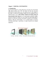
Page 9: ...atisfy most of the applications in the industrial market such as POS KIOSK Industrial Automation HMI and Programmable Control System It s a PC based system with DDR2 SDRAM VGA LCD controller four COM...

Page 10: ...em memory LCD Support Intel GMA 950 Integrated Graphics Engine built in single or dual channel panel support up to 1600 x 1200 18bit Ethernet 2 x Giga LAN Dual Realtek RTL8111B Controller Audio Realte...

Page 11: ...r 10 4 R10I37T OFM3 1024x768 16 2M 6bits color 10 4 R10I37T OFP1 800 x 600 262 144 6bit colors 10 4 R10I37T OFU1 800 x 600 262 144 6bit colors 12 1 R12I37T OFL1 800x600 262 144 6bit colors 15 R15I37T...

Page 12: ...C 3 Knob Brightness Adjustment Knob 4 DC IN DC 12V Input 5 PS 2 The Motherboard provides two PS 2 interface The PS 2 connector supports Keyboard Green and Mouse 6 COM1 port One COM port supports RS232...

Page 13: ...ernal equipment as Keyboard and Mouse a Please use external USB DVD ROM to run the O S and Driver setting as picture showed below USB Cable 2 3 Driver Installation s Manual and Driver CD that contains...

Page 14: ...nel PC s touch device is used RS232 interface touch controller card via the COM3 port inside Panel PC When the touch driver installed either for ELO or Premier Touch systems it will detect COM4 port a...

Page 15: ...For Driver Installation please install the ELO Touch System Touch Tools CD for Windows XP Windows 2000 Windows Me Windows 98 Windows 95 Windows NT Windows CE 2 x 3 0 4 x Windows XP Embedded Windows 3...

Page 16: ...inishing the installation please follow the steps to test the configuration utility Step 1 Enter My Computer click the Elo touchscreen shortcut function Step 2 Click Align function key to go to next s...

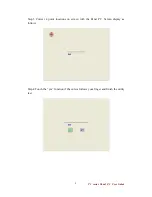
Page 17: ...3 Correct 4 point locations on screen with the Panel PC Screen display as follows Step 4 Touch the yes function if the cursor follows your finger and finish the utility test T5 series Panel PC User Gu...

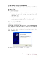
Page 18: ...ort The calibration and draw test of touch panel are done by this utility Besides users can add or remove for new RS 232 or PS 2 touch panel devices Follow these steps to install TouchKit Step 1 Put t...

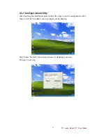
Page 19: ...installation please follow the steps to test the configuration utility Step 1 Click the TouchKit shortcut function in the desktop Step 2 Enter General function and choose the language you need Then g...

Page 20: ...tep 3 Correct 4 point locations on screen with the Panel Screen display as follows Step 4 Play Yes to continue if 4 points calibration test is fine and finish the test T5 series Panel PC User Guide 12...

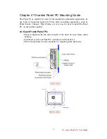
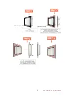
Page 21: ...roaches such as Panel Mount Chassis Open Frame are very easy for user to install the Panel PC As the pictures guided 4 1 Open Frame Panel PC Panel is aligned with the same height of the front of open...

Page 22: ...Panel PC size VESA Mount Dimension Panel PC size VESA Mount Dimension 8 4 75 x 75 mm 17 75 x 75 mm 100 x 100 mm 10 4 75 x 75 mm 19 75 x 75 mm 100 x 100 mm T5 series Panel PC User Guide 14...

Page 23: ...e height of the front of open frame metal housing Touch Glass is higher than Open frame metal housing Customers can fix our Panel PC with their fixture max 12mm VESA mount holes are also available for...

Page 24: ...T5 series Panel PC User Guide 16 note Not support 6 4 and 6 5...

Page 25: ...is aligned with the same height of the front of open frame metal housing Customers can fix our Panel PC with their fixture by M3 screws VESA mount holes are also available for mounting from back side...

Page 26: ...T5 series Panel PC User Guide 18...

Page 27: ...er four screws 100 x 100 mm 75 x 75 mm T5 series Panel PC User Guide 19 Panel PC size VESA Mount Dimension Panel PC size VESA Mount Dimension 6 4 75 x 75 mm 12 1 75 x 75 mm 6 5 75 x 75 mm 15 75 x 75 m...

Page 28: ...al mode Panel CRT the resolution of external display may be recommended equal to the CMOS setting for panel Flat Panel Type Lower resolution than CMOS setting in Windows may cause indistinct display R...

Page 29: ...s as built in display The extended mode is not available for I370 3 When you use CF card as storage of Operation System you need to use Fixed Disk Mode type Compact Flash Card instead of removable dis...

Reviews: