background image


20 

5.7"~32" Panel Mount Display User Manual 

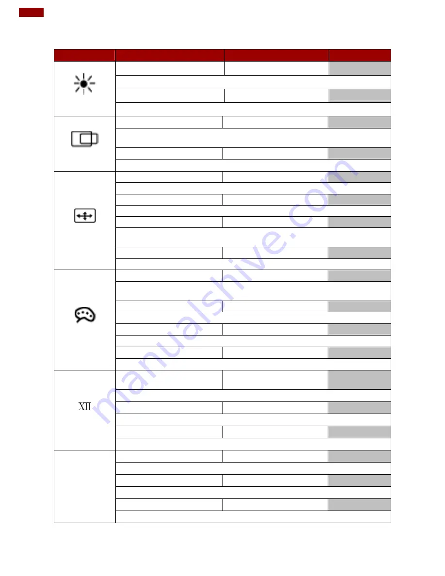
3.2 OSD Menu Navigation 

OSD Icon 

Sub-menu 

Settings  

Note 


BRICONTRAST 

BRIGHTNESS 

slider bar 

Default 50 

Use to adjust the screen’s brightness. Range 0 to 100 

CONTRAST 

slider bar 

Default 50 

Use to adjust the screen’s contrast. Range 0 to 100 


POSITION 

H POSITION 

slider bar 

Default 50 

Use to adjust the image to the left or right on the screen.  
Range 0 to 100 

V POSITION 

slider bar 

Default 50 

Use to adjust the image up or down on the screen. Range 0 to 100 


IMAGE 

AUTO 

Select and execute  


Use to choose the best settings for the current input signal 

CLOCK 

slider bar 

Default 50 

Use to adjust the value of horizontal image. Range 0 to 100 

PAHSE 

slider bar 

Default 50 

Use to adjust the phase control (Phase adjustment may be required to 
optimize the display quality) 

WHITE BALANCE 

Select and execute  


Use to set RGB signal voltage level 


COLOR 

USER 

R.G.B slider bar 


Choose RED/GREEN/BLUE to set value of color temperature brightness to 
suit your own preference 

9300K 

Select and execute  


Use to set value of monitor for the CIE coordinate 9300 color temperature 

6500K 

Select and execute  


Use to set value of monitor for the CIE coordinate 6500 color temperature 

ADC RIGHTNESS 

slider bar  

Default 50 

Set value of monitor for ADC Brightness. Range 0 to 100 


GAMMA 

GAMMA 0 

Select and execute 

Default 
GAMMA0 

Choose the parameter of GAMMA 0 as default setting. 

GAMMA 1 

Select and execute 


Choose the parameter of GAMMA 1 as default setting. 

GAMMA 2 

Select and execute 


Choose the parameter of GAMMA 2 as default setting. 

OP 

OPTION 

VR Brightness 

ON/OFF 

Default OFF 

Choose the brightness control mode by VR control 

Volume 

slider bar 

Default 10 

Use to set value of Volume 

Speaker 

ON/OFF 

Default OFF 

Use to set value of Volume Speaker 


Summary of Contents for R19L-PM Series

Page 1: ...Please read this instructions before operating the device and retain them for future reference Panel Mount Display 5 7 32 User Manual Version 1 4 Document Part Number 91521110101F ...

Page 2: ... 2 LED Indicators 11 Chapter 2 Installation 12 2 1 Wiring Requirements 13 2 2 Mounting Guide 14 2 2 1 Panel Mount 14 2 2 2 VESA Mount 15 2 3 Cable Mounting Considerations 16 2 4 Connecting Power 16 2 5 Connecting Peripherals 17 2 5 1 VGA Connector 17 2 5 2 HDMI Connector 17 Chapter 3 Operating the Device 18 3 1 Turning on the System 19 3 2 OSD Menu Navigation 20 3 3 Troubleshooting Guide 21 Append...

Page 3: ...If the customer discovers a defect we will at his her option repair or replace the defective product at no charge to the customer provide it is returned during the warranty period of one year with transportation charges prepaid The returned product must be properly packaged in its original packaging to obtain warranty service If the serial number and the product shipping data differ by over 30 day...

Page 4: ...at is important for you to know Caution A Caution alert indicates potential damage to hardware and explains how to avoid the potential problem Attention Unealerted attention indique un dommage possible à l équipement et explique comment éviter le problem potentiel Warning An Electrical Shock Warning indicates the potential harm from electrical hazards and how to avoid the potential problem Avertis...

Page 5: ...me précaution Placer toutes les composantes électroniques sur une surface conçue pour dissiper les charge ou dans un sac anti statique lorsqu elles ne sont pas dans le chassis Safety Precautions For your safety carefully read all the safety instructions before using the device Keep this user manual for future reference Always disconnect this equipment from any AC outlet before cleaning Do not use ...

Page 6: ... Manual contains detailed description on how to use the display its components and features Note Some pictures in this guide are samples and can differ from actual product Document Revision History Version Date Note 1 0 25 Aug 2017 New document release 1 1 22 Nov 2018 Add 24 inch display 1 2 2 Feb 2019 Revise format 1 3 1 Sep 2020 Standard video input change to 1 x VGA D sub 15 1 x HDMI Type A 1 4...

Page 7: ...roduction This chapter gives you product overview describes features and hardware specification You will find all accessories that come with the display device in the packing list Mechanical dimensions and drawings included in this chapter ...

Page 8: ... remove the box and unpack your display Please check if all the items listed below are inside your package If any of these items are missing or damaged contact us immediately Standard factory shipment list Display User Manual Hardcopy Black screw bolts Varies by product Part No 91521110101F Varies by product 110 240V AC Power Adapter Power Cord VGA Cable Varies by product Varies by country Part No...

Page 9: ...h other input terminals based on your order Note Notice that input and output connectors vary by product size and specifications The picture above shows only a prototype model for information purposes only The location of OSD panel may vary by model Refer to a product datasheet for more details Description Description RS232 Remote control Optional HDMI RS232 USB for Touch Optional DC in VGA OSD Co...

Page 10: ...PC to a monitor Example A notebook PC to a monitor HDMI Transmits and protects copyrighted digital video and audio Example An HD tuner to an HD ready TV 1 6 OSD Control Panel 1 6 1 Control Buttons OSD control panel varies by product specifications Refer to a product datasheet to check the OSD control panel type of a particular model Type A Icon Function Decrease the value Select up Increase the va...

Page 11: ...wer switch Exit Auto adjustment Enter Call main OSD menu 1 6 2 LED Indicators LED indicators are located on the OSD control panel the rear side of the display Icon Description Function Power Lights up in Green when the monitor turn on Stand by Lights up in Orange when the device cannot detect any input source ...

Page 12: ...Mount Display User Manual Chapter 2 Installation This chapter provides hardware installation instructions and mounting guide for all available mounting options Pay attention to cautions and warning to avoid any damages ...

Page 13: ...sed that you label wiring to all devices in the system Caution Attention Do not run signal or communication wiring and power wiring in the same conduit To avoid interference wires with different signal characteristics i e different interfaces should be routed separately Be sure to disconnect the power cord before installing and or wiring your device Verify the maximum possible current for each wir...

Page 14: ...lessure 2 2 1 Panel Mount The Panel Mount Display comes with clamp mounts that enable you to install the unit onto a wall where space has been cut out to accommodate the rest of the hardware Installation Instruction 1 Make a cutout on the fixture ex wall according to the cutout dimensions of the display Based on the drawing mark screw holes on a front side of the fixture Place display on the fixtu...

Page 15: ...ount Display comes with VESA Mount holes for mounting Installation Instruction 1 Screw VESA bracket to the fixture ex swing arm with four VESA screws 2 Place the device on VESA bracket Notice that VESA stand and mounting kit are not provided by Winmate ...

Page 16: ... installation Attention Éteindre l appareil et débrancher tous les périphériques avant l installation 2 4 Connecting Power This section provides information on how to use connectors on the Panel Mount Display Be cautious while working with these modules Please carefully read the content of this chapter in order to avoid any damages Installation instruction 1 Connect the AC cord to the AC IN termin...

Page 17: ...ble to the VGA connector in the rear of motherboard and plug the other end to the monitor Secure cable connectors with hexagonal copper pillars M3x4mm Pin assignment and signal names for VGA connector 2 5 2 HDMI Connector Plug HDMI signal cable to the HDMI connector on the rear side of PC system and plug the other end to the monitor Pin assignment and signal names for HDMI connector Pin Signal Nam...

Page 18: ...18 5 7 32 Panel Mount Display User Manual Chapter 3 Operating the Device In this chapter you will find instructions on how to operate the display ...

Page 19: ...o turn on the system 1 Connect the power adapter cable to the DC IN of the display 2 Connect the power cord to the power adapter 3 Connect the power cord to a power outlet 4 Press the power button located on the OSD control panel on the rear to turn on the system ...

Page 20: ...mize the display quality WHITE BALANCE Select and execute Use to set RGB signal voltage level COLOR USER R G B slider bar Choose RED GREEN BLUE to set value of color temperature brightness to suit your own preference 9300K Select and execute Use to set value of monitor for the CIE coordinate 9300 color temperature 6500K Select and execute Use to set value of monitor for the CIE coordinate 6500 col...

Page 21: ...l cable is firmly seated in the socket Check if the output level matches the input level of your computer Make sure the signal timings of the computer system are within the specification of the monitor If your computer was working with a CRT monitor you should check the current signal timing and turn off your computer before you connect the VGA Cable to this monitor The position of the screen is n...

Page 22: ...22 5 7 32 Panel Mount Display User Manual Appendix This chapter contains additional product information including troubleshooting guide and frequency table ...

Page 23: ...8 4 3 V V V V V V V V V V V V V V V V V V V V V 1280 720 16 9 720P V V V V V V V V V V V V V V V V V 1280 768 V V V 1280 800 16 10 V V V V V V V V V 1280 1024 5 4 V V V V V V V V V V V V 1366 768 V V V 1400 1050 4 3 V V V 1440 900 16 10 V V V V V V 1600 1200 4 3 V V V 1680 1050 16 10 V V V V V V 1920 1080 16 9 1080P V V V V V V V V V V V V V V V 1920 1200 16 10 V V V Appendix B Frequency Table Fre...

Page 24: ...Winmate Inc 9F No 111 6 Shing De Rd San Chung District New Taipei City 24158 Taiwan R O C www winmate com Copyright Winmate Inc All rights reserved ...

Reviews: