Winmate R15L600-65A1FTP User Manual Download Page 25


25 

Appendix 

Appendix D: Projected Capacitive Touch Screen 

Projected Capacitive Touch (P-CAP) technology is a variant of capacitive touch technology. All 
PCAP  touch  screens  are  made  up  of  a  matrix  of  rows  and  columns  of  conductive  material, 
layered  on  sheets  of  glass.  Projected  capacitive  technology  enables  touches  to  be  sensed 
through  a  protective  layer  in  front  of  a  display,  allowing  touch  monitors  to  be  installed  behind 
store  windows  or  vandal-resistant  glass.  In  addition,  the  surface  material  is  glass,  which  is 
scratch-resistant, durable, and reliable in harsh environments. 


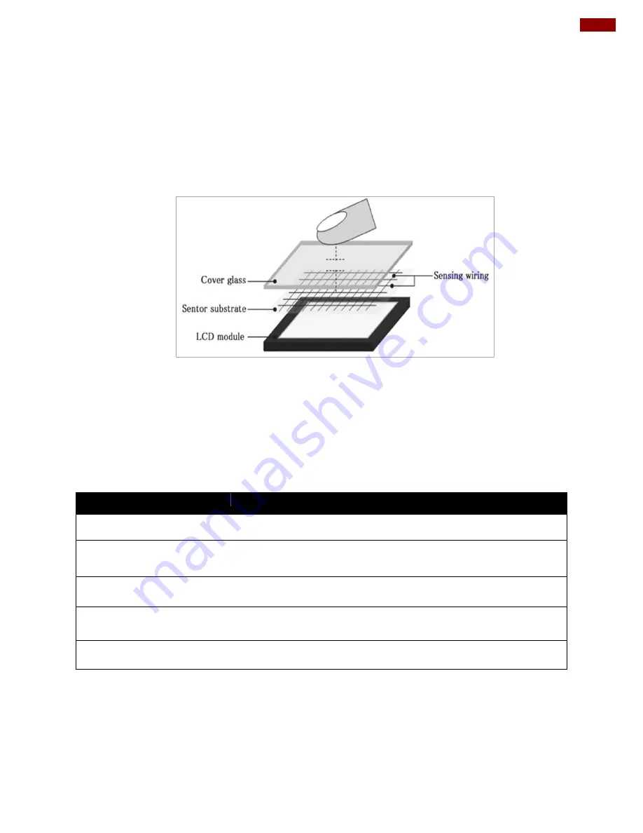
The  operational  theory  of  a  P-CAP  touch  screen  begins  with  two  patterned  Indium  Tin  Oxide 
(ITO) layers under a glass substrate cover which create a X-axis and Y-axis electric field. These 
electric  fields  project  above  the  glass  surface  between  adjacent  ITO  traces.  When  a  finger 
approaches the glass surface, a new balance in the electric field will be established between the 
finger  and  the  corresponding  X-axis  and  Y-axis.  The  controller  IC  will  locate  the  ITO  traces 
exhibiting capacitance changes to pinpoint the finger touch accurately. 

Brief Specifications 

Subject


Details


Input Method 

Finger, gloved hand 

Positional Accuracy 

<1.5% of reported position in recommended viewing area. 

Resolution 

Touch point density is based on controller resolution 

Touch Activation Force 

No minimum touch activation force is required 

Light Transmission 

Up to 90% per ASTM D1003-92 

Summary of Contents for R15L600-65A1FTP

Page 1: ...ease read this instructions before operating the device and retain them for future reference 15 Full IP65 P Cap Stainless Display R15L600 65A1FTP User Manual Version 1 0 Document Part Number 91521110103T ...

Page 2: ...VESA Mount 12 2 3 Cable Mounting Considerations 13 2 4 Connecting Power 13 2 5 Connecting Peripherals 14 2 5 1 Power Cable 15 2 5 2 USB Cable for Touch 15 2 5 3 RS 232 Cable for Remote Control 16 2 5 4 VGA Cable 17 2 5 5 USB Cable for Touch 17 Chapter 3 Operating the Device 18 3 1 Turning On and Off the Device 19 3 2 OSD Menu Navigation 20 3 3 Troubleshooting Guide 21 Appendix 22 Appendix A Hardwa...

Page 3: ...If the customer discovers a defect we will at his her option repair or replace the defective product at no charge to the customer provide it is returned during the warranty period of one year with transportation charges prepaid The returned product must be properly packaged in its original packaging to obtain warranty service If the serial number and the product shipping data differ by over 30 day...

Page 4: ...at is important for you to know Caution Attention A Caution alert indicates potential damage to hardware and explains how to avoid the potential problem Unealerted attention indique un dommage possible à l équipement et explique comment éviter le problem potentiel Warning Avertissement An Electrical Shock Warning indicates the potential harm from electrical hazards and how to avoid the potential p...

Page 5: ...arte CPU Les équipements électroniques moderns sont très sensibles aux décharges d électricité statique Toujours utiliser un bracelet de mise à la terre comme précaution Placer toutes les composantes électroniques sur une surface conçue pour dissiper les charge ou dans un sac anti statique lorsqu elles ne sont pas dans le chassis Safety Precautions For your safety carefully read all the safety ins...

Page 6: ...precaution use a grounding wrist strap at all times Place all electronic components in a static dissipative surface or static shielded bag when they are not in the chassis About This User Manual This User Manual provides information about using the Winmate 15 Full IP65 P Cap Stainless Display The documentation set provides information for specific user needs and includes Full IP65 P Cap Stainless ...

Page 7: ...roduction This chapter gives you product overview describes features and hardware specification You will find all accessories that come with the display device in the packing list Mechanical dimensions and drawings included in this chapter ...

Page 8: ... 15 TFT LCD VGA video input USB for touch Full IP65 water and dust proof SUS 304 stainless steel enclosure Supports VESA mount Optical bonding for moisture prevention Suitable for food and pharmaceutical industry 1 3 Package Contents Carefully remove the box and unpack your display Please check if all the items listed below are inside your package If any of these items are missing or damaged conta...

Page 9: ...1 4 Product Overview This section describes physical appearance of the Display 15 inch R15L600 65A1FTP Unit mm 1 5 Physical Buttons and LED Indicators Physical buttons and LED indicators located on the rear side of the Display ...

Page 10: ...p when without OSD menu ESC AUTO Press to exit the menu or auto adjustment when without OSD menu OK MENU Press to confirm the action or to call main OSD menu Power On Off Press to power on or power off the device LED Indicators LED Type Status Description On Power is on Off Power is off On System is in standby mode Off System is idle 1 6 Connector Description Full IP65 P Cap Display has M25 type c...

Page 11: ...er 2 Installation Chapter 2 Installation This chapter provides hardware installation instructions and mounting guide for all available mounting options Pay attention to cautions and warning to avoid any damages ...

Page 12: ... Be sure to disconnect the power cord before installing and or wiring your device Verify the maximum possible current for each wire gauge especially for the power cords Observe all electrical codes dictating the maximum current allowable for each wire gauge If the current goes above the maximum ratings the wiring could overheat causing serious damage to your equipment Be careful when handling the ...

Page 13: ...als before installation Éteindre l appareil et débrancher tous les périphériques avant l installation 2 4 Connecting Power This section provides information on how to use connectors on Display Be cautious while working with these modules Please carefully read the content of this chapter in order to avoid any damages Installation instruction 1 Connect the AC cord to the AC IN terminal on the AC ada...

Page 14: ...monitor settings from the OSD menu when switching between these sources Note Notice that standard input terminals include VGA Your device may be equipped with USB for touch DVI input terminals based on your order Perform the connections as shown below Caution Attention To maintain device s IP65 rating close the I O and tighten protection caps when I O is not used Pour maintenir la norme IP65 de l ...

Page 15: ...Display has M25 type connectors Use power cable to connect display to the source of power The display support 12V DC power input 2 5 2 USB Cable for Touch The display may have optional M25 type USB connector for touch based on your order Use USB cable to connect touch ...

Page 16: ... 15 Full IP65 P Cap Stainless Display User Manual 2 5 3 RS 232 Cable for Remote Control The display may have optional M25 type serial port connector based on your order Use serial cable to adjust monitor ...

Page 17: ...n 2 5 4 VGA Cable The display has M25 type VGA connector Use VGA cable to connect the display to other external devices 2 5 5 USB Cable for Touch The display has M25 type USB connector for touch Use USB cable to connect touch ...

Page 18: ...18 15 Full IP65 P Cap Stainless Display User Manual Chapter 3 Operating the Device In this chapter you will find instructions on how to operate the display ...

Page 19: ...fits to the connector then tighten the O ring by turning it clockwise to secure the connection 3 Connect the AC adapter to the power cord 4 Plug the power cord to an electrical outlet 5 Plug the Power button to turn on the device Note When the system hangs press the Reset button to restart the device To shut down your device do the following disconnect the power cord and the device will automatica...

Page 20: ...tage level COLOR USER R G B slider bar Choose RED GREEN BLUE to set value of color temperature brightness 9300K Select and execute Use to set value of monitor for the CIE coordinate 9300 color temperature 6500K Select and execute Use to set value of monitor for the CIE coordinate 6500 color temperature ADC RIGHTNESS slider bar Default 50 Set value of monitor for ADC Brightness Range 0 to 100 GAMMA...

Page 21: ...itor If your computer was working with a CRT monitor you should check the current signal timing and turn off your computer before you connect the VGA Cable to this monitor The position of the screen is not in the center Adjust the H position and V position or Perform the Auto adjustment The screen is too bright too dark Check if the brightness or contrast control is at the appropriate position not...

Page 22: ...22 15 Full IP65 P Cap Stainless Display User Manual Appendix This chapter contains additional product information including troubleshooting guide and frequency table ...

Page 23: ...wing Angles 80 80 70 70 Max Colors 16 7M 8 bits Touch Projected capacitive Power Requirements Input Voltage 12V DC Power Consumption 20W Physical Characteristics Housing Stainless steel Dimensions 396 x 310 x 49mm W x H x D Mounting Mounting hole for VESA 100 x 100 Gross Weight 11 kg Net Weight 11 5 kg Environment Limits Operating Temperature 20 C to 60 C Ambient Relative Humidity 10 to 95 RH non ...

Page 24: ... the power cable from any AC outlet When cleaning Use water up to 80 C to clean the housing Wipe the screen with a clean soft lint free cloth This removes dust and other particles The display area is highly prone to scratching Does not use ketene type material for example Acetone Ethyl alcohol toluene ethyl acid or Methyl chloride to clear the panel It may permanently damage the panel and void the...

Page 25: ...reen begins with two patterned Indium Tin Oxide ITO layers under a glass substrate cover which create a X axis and Y axis electric field These electric fields project above the glass surface between adjacent ITO traces When a finger approaches the glass surface a new balance in the electric field will be established between the finger and the corresponding X axis and Y axis The controller IC will ...

Page 26: ...________________________ ______________________________________________________________________________ ______________________________________________________________________________ ______________________________________________________________________________ ______________________________________________________________________________ ___________________________________________________________...

Page 27: ...________________________ ______________________________________________________________________________ ______________________________________________________________________________ ______________________________________________________________________________ ______________________________________________________________________________ ___________________________________________________________...

Page 28: ...Winmate Inc 9F No 111 6 Shing De Rd San Chung District New Taipei City 24158 Taiwan R O C www winmate com Copyright Winmate Inc All rights reserved ...

Reviews: