ID30 Motherboard User Manual
9
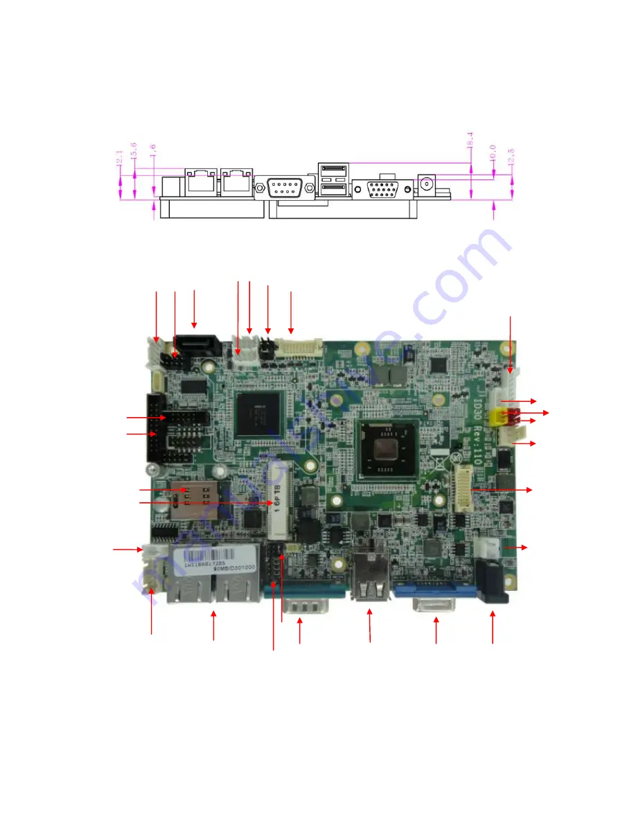
2.3 Jumpers and Connectors
TOP
USB
1
S
A
T
A1
CPU
Fan
DVI1
12V
DC
in
P
AN
EL
C
N10
COM2
R
J45
5V
L
VD
JP2
12V in
AU
DIO1
ON
3
VGA
OM
2
JP1
JP3
COM3
J2/J3
SIM Slot
MiniPCIe
Page 1: ...ID30 Motherboard 3 5 Fanless SBC w Intel Atom D2700 2 13GHz Processor VGA LVDS Dual Giga Ethernet and Mini PCIe Interface USER MANUAL Version 1 0 ...
Page 2: ...ss a digital device pursuant to part 15 of the FCC rules These limits are designed to provide reasonable protection against harmful interference when the equipment is operated in a commercial environment This equipment generates uses and can radiate radio frequency energy and if not installed and used in accordance with the instruction manual may cause harmful interference to radio communications ...
Page 3: ... Applications that are described in this manual are for illustration purposes only Winmate Communication Inc makes no representation or warranty that such application will be suitable for the specified use without further testing or modification Warranty We warrant that each of its products will be free from material and workmanship defects for a period of one year from the invoice date If the cus...
Page 4: ...h your distributor sales representative or our customer service center for technical support if you need additional assistance You may have the following information ready before you call Product serial number Peripheral attachments Software OS version application software etc Description of complete problem The exact wording of any error messages In addition free technical support is available fr...
Page 5: ...e damaged by sudden power surges Only experienced electronic personnel should open the PC chassis Caution Always ground yourself to remove any static charge before touching the CPU card Modern electronic devices are very sensitive to static electric charges As a safety precaution use a grounding wrist strap at all times Place all electronic components in a static dissipative surface or static shie...
Page 6: ...so that people cannot step on it Do not place anything over the power cord 10 All cautions and warnings on the equipment should be noted 11 If the equipment is not used for a long time disconnect it from the power source to avoid damage by transient over voltage 12 Never pour any liquid into an opening This could cause fire or electrical shock 13 Never open the equipment For safety reasons only qu...
Page 7: ...ID30 Motherboard User Manual VII Revision History Version Date Note Author 1 0 2011 12 16 Initial Draft Henry Hsu ...
Page 8: ... 2 3 JUMPERS AND CONNECTORS 9 2 4 JUMPER SETTING 11 2 5 CONNECTORS AND PIN ASSIGNMENT 13 CHAPTER 3 GRAPHIC DRIVER INSTALLATION 20 3 1 STANDARD CMOS FEATURE 20 3 2 PANEL RESOLUTION SETTING 24 CHAPTER 4 CHIPSET DRIVER INSTALLATION 27 4 1 STANDARD CMOS FEATURES 27 CHAPTER 5 ETHERNET DRIVER INSTALLATION 31 INSTALLATION OF ETHERNET DRIVER 31 CHAPTER 6 AUDIO DRIVER INSTALLATION 35 6 1 INTRODUCTION 35 6 ...
Page 9: ...ard User Manual 1 General Information This chapter includes the ID30 Motherboard background information Sections include Introduction Feature Motherboard Specification Function Block Board Dimensions C H A P T E R 1 ...
Page 10: ...d USB 2 0 connectors Two Connector Four Pin Header Additionally ID30 SBC build in a 12V DC IN power adapter Thus the ID30 SBC is designed to satisfy most of the applications in the industrial computer market such as Gaming POS KIOSK Industrial Automation and Programmable Control System It is a compact design to meet the demanding performance requirements of today s business and industrial applicat...
Page 11: ...der for Front Panel 2x5 1 x 8pins pin header for 5V 12V external power 1 x 3pins pin header for CPU Fan 1 x 2pins pin header for 5V external power 1 x 2pins pin header for 12V external power 1 x 12pins pin header for Front Audio 2x6 2 x 8pins pin header for USB 2X4 1 x 10pins Digital I O 2x5 1 x 20pins pin header for COM 3 4 RS232 2X10 1 x 10pins pin header for COM2 2X5 1 x 2 pin Power input conne...
Page 12: ...A LVDS SO DIMM x 1 DDR3 800 1066 Max 4GB Mini PCIe LAN USB 1GB s 480MB s Audio Realtek ALC655 Super IO Realtek ALC655 BIOS Realtek ALC655 Intel NM10 Chipset SATA II DVI A AM MI I 3GB s F Fi in nt te ek k F F8 81 18 86 65 5 R Re ea al lt te ek k A AL LC C8 88 86 6 ...
Page 13: ...ID30 Motherboard User Manual 5 1 5 Board dimensions ...
Page 14: ...ons This chapter provides information on how to use the jumps and connectors on the ID30 Motherboard The Sections include Memory Module Installation I O Equipment Installation Setting the Jumpers Connectors on ID30 Motherboard C H A P T E R 2 ...
Page 15: ...mly insert the SO DIMM at an angle into its slot Align the SO DIMM on the slot such that the notch on the SO DIMM matches the break on the slot Step 2 Press downwards on SO DIMM until the retaining clips at both ends fully snap back in place and the SO DIMM is properly seated Caution The SO DIMM only fits in one correct orientation It will cause permanent damage to the development board and the SO...
Page 16: ...ower cable to the outlet The VGA connector is a standard 15 pin D SUB connector 2 2 4 Ethernet interface The Motherboard is equipped with Broadcom BCM57780 chipset which is fully compliant with the PCI 10 100 1000 Mbps Ethernet protocol compatible It is supported by major network operating systems The Ethernet ports provide two standard RJ 45 jacks 2 2 5 USB ports Four USB devices Two with pin hea...
Page 17: ...Motherboard User Manual 9 2 3 Jumpers and Connectors TOP USB1 SATA1 CPU Fan DVI1 12V DC in PANEL CN10 COM2 RJ45 5V LVDS1 JP2 12V in AUDIO1 CON3 VGA COM1 USB 12V USB3 CON2 JP1 JP3 COM3 J2 J3 SIM Slot MiniPCIe ...
Page 18: ...ID30 Motherboard User Manual 10 BOTTOM MiniPCIe for SSD SO DIMM ...
Page 19: ... standard cable to make most connections The jumper setting diagram is as below If a jumper shorts pin 1 and pin 2 the setting diagram is shown as the right one The following tables list the function of each of the board s jumpers Label Function Note JP4 Clear CMOS 3x1 header pitch 2 0mm JP2 RS232 RS422 RS485 Selector 2x3 header pitch 2 0mm JP3 RS232 RS422 RS485 Selector 3x4 header pitch 2 0mm CON...
Page 20: ...ID30 Motherboard User Manual 12 2 4 3 JP3 RS232 RS422 RS485 Selector for CON port 2 4 4 CON2 LCD Panel Voltage Select ...
Page 21: ...COM2 COM2 for RS232 2x5 header COM3 Left COM3 for RS232 2x5 header COM3 Right COM4 for RS232 2x5 header AUDIO1 Audio connector 2x6 header USB1 USB PIN HEADER 4x2 Pin Header USB3 USB PIN HEADER 4x2 Pin Header CPU_FAN FAN CONNECTOR 3x1 Pin Header PANEL1 System Function Connector 5x2 header pitch 2 0mm 12V1 12V External Power 2x1 header pitch 2 0mm 5V1 5V External Power 2x1 header pitch 2 0mm CN10 12...
Page 22: ...DN 3 GND 4 LVDS_TX0_DP 5 GND 6 LVDS_TX1_DN 7 GND 8 LVDS_TX1_DP 9 GND 10 LVDS_TX2_DN 11 N C 12 LVDS_TX2_DP 13 LCDVDD 14 LVDS_CLK_DN 15 LCDVDD 16 LVDS_CLK_DP 17 LCDVDD 18 LVDS_TX3_DN 19 LCDVDD 20 LVDS_TX3_DP 2 5 2 JP1 Digital Panel Backlight Brightness Control Pin No SYMBOL 1 VCC 2 Black Light Control 3 GND ...
Page 23: ...bond I O serial port 10x2 header pitch 2 0mm Pin No SYMBOL 1 12V 2 12V 3 12V 4 GND 5 Black Light Control 6 GND 7 Black Light EN 5V Pin No SYMBOL Pin No SYMBOL 20 GND 19 GND 18 FK NRI2 17 FK NDTR2 16 FK NCTS2 15 FK NSOUT2 14 FK NRTS2 13 FK NSIN2 12 FK NDSR2 11 FK NDCD2 10 GND 9 GND 8 FK NRI1 7 FK NDTR1 6 FK NCTS1 5 FK NSOUT1 4 FK NRTS1 3 FK NSIN1 2 FK NDSR1 1 FK NDCD1 ...
Page 24: ...O1 Audio Connector USB Pin SYMBOL Pin SYMBOL 2 USBVCC 1 USBVCC 4 USB_P6 3 USB_P7 6 USB_P6 5 USB_P7 8 GND 7 GND Pin SYMBOL Pin SYMBOL 2 HD_LED 1 PW_LED 4 HD_LED 3 PW_LED 6 RT_BT1 5 PW_BT1 8 RT_BT2 7 PW_BT2 10 5VSB 9 RSEV Pin SYMBOL Pin SYMBOL 2 AZ_FOUT_L 1 AZ_FOUT_R 4 AUGND 3 5VA 6 LINE1_L 5 LINE1_R 8 MIC1_L 7 MIC1_R 10 SW_D 9 AUGND 12 SW_C 11 SW_B 1 4 5 7 3 8 6 2 1 3 5 7 9 2 4 6 8 10 ...
Page 25: ...IDO1 Digital I O Connector 2 5 1 J2 J3 Amplifier 2 5 1 COM2 Serial port COM2 Pin SYMBOL Pin SYMBOL 2 Vcc 1 GND 4 Out1 3 Out3 6 Out0 5 Out2 8 IN1 7 IN3 10 IN0 9 IN2 Pin SYMBOL Pin SYMBOL 10 GND 9 GND 8 NRI1A 7 NDTR1A 6 NCTS1A 5 NTXD1A 4 NRTS1A 3 NRXD1A 2 NDSR1A 1 NDCD1A 9 7 5 3 1 10 8 6 4 2 ...
Page 26: ...OL Pin No SYMBOL 1 GND 2 TMDSB_DATA0 3 GND 4 TMDSB_DATA0 5 DVIC_LVDS_DET 6 TMDSB_DATA1 7 DVIC_BKLTEN 8 TMDSB_DATA1 9 DVIC_VDDEN 10 TMDSB_DATA2 11 DVI_HOT_DETECT 12 TMDSB_DATA2 13 LCDVDD 14 TMDSB_BLK 15 LCDVDD 16 TMDSB_BLK 17 V5S 18 DVI1_DDC_CLK_R 19 V5S 20 DVI_DDC_DAT_R ...
Page 27: ...0 Motherboard User Manual 19 Graphic Driver Installation This chapter offers information on the chipset software Installation utility Installation of Graphic Driver Panel Resolution Setting C H A P T E R 3 ...
Page 28: ...ion Device The Intel Graphic Drivers should be installed first and it will enable Video Controller VGA compatible Follow the instructions below to complete the installation You will quickly complete the installation Step 1 Insert the CD that comes with the Motherboard Open the file document Graphic Driver Step 2 Click on setup to execute the setup ...
Page 29: ...ID30 Motherboard User Manual 21 Step 3 Click on Next to install Driver Step 4 Click on Yes to agree License ...
Page 30: ...ID30 Motherboard User Manual 22 Step 5 Click on Next to install Driver Step 6 Click on Next to install Driver ...
Page 31: ...ID30 Motherboard User Manual 23 Step 7 Click on Yes I want to restart this computer now to go on ...
Page 32: ...0 Motherboard User Manual 24 3 2 Panel Resolution Setting Step 1 Right click the desktop and then click Properties Step 2 In the Display Properties dialog box click the Settings tab Step 3 Click on Monitor ...
Page 33: ...ID30 Motherboard User Manual 25 Step 4 Click on Hide modes that this monitor cannot display to remove this option Step 5 Click on Setting then could choose 32bit color qualify ...
Page 34: ...D30 Motherboard User Manual 26 Chipset Driver Installation This chapter offers information on the chipset software Installation utility Installation of Chipset Driver Further information C H A P T E R 4 ...
Page 35: ...ser Manual 27 Chapter 4 Chipset Driver Installation 4 1 Standard CMOS Features Setp 1 Insert the CD that comes with the motherboard Open the file document Chipset Driver Setp 2 Click on infinst_auto exe to install driver ...
Page 36: ...ID30 Motherboard User Manual 28 Setp 3 Click on Yes to agree License Setp 4 Click on Next to install driver ...
Page 37: ...ID30 Motherboard User Manual 29 Setp 5 Click on Next to install driver Step 7 Click on Yes I want to restart this computer now to go on ...
Page 38: ...therboard User Manual 30 Ethernet Driver Installation This chapter offers information on the Ethernet software installation utility Sections include Introduction Installation of Ethernet Driver C H A P T E R 5 ...
Page 39: ...ou are using in the ID30 Motherboard before installing the Ethernet drivers Follow the steps below to complete the installation of the Broadcom BCM57780 Gigabit Ethernet controller LAN drivers You will quickly complete the installation Step 1 Right click the desktop and then click Properties Step 2 In the Other device dialog box click the Settings tab ...
Page 40: ...ID30 Motherboard User Manual 32 Step 2 Click on Update Driver to execute the setup Step 4 Click on Browse my computer for driver software to install driver ...
Page 41: ...ID30 Motherboard User Manual 33 Step 5 Choose the path to install driver Setp 6 Click on Close and go on ...
Page 42: ...0 Motherboard User Manual 34 Audio Driver Installation This chapter offers information on the Audio software installation utility Sections include Introduction Installation of Audio Driver C H A P T E R 6 ...
Page 43: ...o stereo ADCs that can support a stereo microphone and feature Acoustic Echo Cancellation AEC Beam Forming BF and Noise Suppression NS technology 6 2 Installation of Audio Driver The users must make sure which operating system you are using in the IA30 Motherboard before installing the Audio drivers Follow the steps below to complete the installation of the Realtek ALC655 Audio drivers You will qu...
Page 44: ...ID30 Motherboard User Manual 36 Step 2 Click on Yes to install driver Step 3 Click on Yes I want to restart my computer now to finish installation ...
Page 45: ...ID30 Motherboard User Manual 37 Fintek COM Port Driver Installation This chapter describes the step by step method to install the Fintek COM port driver C H A P T E R 7 ...
Page 46: ... the Patch_0408 zip to a folder STEP 3 Double click batch file patch bat will install driver STEP 4 Check driver install success Before the update or update fail After the update and update success STEP 5 You will need to restart your computer for driver install success Type in this command from the Run menu C Windows System32 UserAccountControlSettings exe or uac ...
Page 47: ...herboard User Manual 39 To turn off UAC move the slider to the Never notify position and then click OK If you re prompted for an administrator password or confirmation type the password or provide confirmation ...
Page 48: ...k on move the slider to choose when you want to be notified and then click OK If you re prompted for an administrator password or confirmation type the password or provide confirmation You will need to restart your computer for UAC to be turned off ...
Page 49: ...ID30 Motherboard User Manual 41 AMI BIOS Setup This chapter describes how to set up the BIOS configuration C H A P T E R 8 ...
Page 50: ...rograms The BIOS settings also identify installed devices and establish many special features ENTERING BIOS SETUP You can access the BIOS program just after you turn on your computer Just press the DEL key when the following prompt appears Press DEL to enter Setup When you press DEL to enter the BIOS Setup image the system interrupts the Power On Self Test POST When you first enter the BIOS Setup ...
Page 51: ...highlighted in white Often a text message will accompany it 7 1 Advanced Setting Launch PXE OpROM SETTING DESCRIPTION Disabled Use this setting to ignore all PXE Option ROMs Enabled Use this setting to load PXE Option ROMs To limit the PXE support to particular devices use the function Use device for PXE Default Disabled Launch Storage OpROM SETTING DESCRIPTION Disabled Use this setting to ignore ...
Page 52: ... ROM Priority Selects the PCI Option ROM to launch in case Multiple Option ROMs Legacy ROM and EFI Compatible ROM are present PCI Latency Timer Use this function to select the number of PCI bus clocks to be used for the PCI latency timer ...
Page 53: ...s clocks 192 PCI Bus Clocks Use this setting to program the PCI latency timer to 192 PCI bus clocks 224 PCI Bus Clocks Use this setting to program the PCI latency timer to 224 PCI bus clocks 248 PCI Bus Clocks Use this setting to program the PCI latency timer to 248 PCI bus clocks Default 32 PCI Bus Clocks VGA Palette Snoop This filed controls the ability of a primary PCI VGA controller to share a...
Page 54: ...e Hibernation Enables or Disables System ability to Hibernate This option may be not effective with some OS ACPI Sleep State SETTING DESCRIPTION Suspend Disable System ability to Hibernate OS S3 Sleep State S1 CPU Stop Clock S3 Suspend to RAM Default S3 Suspend to RAM Lock Legacy Resources Enables or Disable Lock of Legacy Resource Default Disable ...
Page 55: ...er Manual 47 S5 RTC Wake Settings SETTING DESCRIPTION Wake system with Fixed Time System wake on alarm event When enabled System will wake on the hr min sec specified Wake system with Dynamic Time Options Enabled Disabled ...
Page 56: ...ther OS OS not optimized for Hyper Threading Technology When Disabled only one thread per enabled core is enabled Execute Disable Bit XD can prevent certain classes of malicious buffer overflow attacks when combined with a supporting OS Windows Server 2003 SP1 Windows XP SP2 SuSE Linux 9 2 RedHat Enterprise 3 Update 3 Limit CPUID Maximum Disabled for Windows XP ...
Page 57: ...ermal Configuration DTS SMM SETTING DESCRIPTION Disabled Uses EC reported temperature values Enabled Uses DTS SMM mechanism to obtain CPU temperature value Critical Temp Reporting Out of spec Uses EC reported temperature values and DTS SMM to handle out of spec ...
Page 58: ...nt in which the OS will shut the system off Active Trip Point Lo Fan Speed Active Trip Point Hi Fan Speed This field enables or disables the smart fan feature At a certain temperature the fan starts turning Once the temperature drops to a certain level it stops turning again Passive TC1 Value Passive TC2 Value Passive TSP Value ...
Page 59: ...ID30 Motherboard User Manual 51 IDE Configuration Configure SATA as Determines how SATA controllers s operate The options are IDE and AHCI ...
Page 60: ...d User Manual 52 Port0 Speed Limit Select Port0 AHCI Speed Limit The options are No Limit GEN1 Rate and GEN2 Rate SATA Port 0 1 Enable or disable SATA Port SATA Port 0 1 Hot Plug Designates this port as Hot Pluggable ...
Page 61: ...ID30 Motherboard User Manual 53 Intel Fast Flash Standy iFFS Support Enable or disable ...
Page 62: ... off support The EHCI ownership change should be claimed by EHCI driver Default Disabled USB transfer time out The time out value for control bulk and Interrupt transfers Default 20 sec Device reset time out The USB mass storage device Start Unit command time out Default 20 sec Device power up delay Maximun time the device will take before it properly reports itself to the Host Controller Auto use...
Page 63: ...Motherboard User Manual 55 Mass Storage Device Mass storage device emulation type AUTO enumerates devices less than 530MB as floppies Forced FDD option can be used to force HDD formatted drive to boot as FDD ...
Page 64: ...ID30 Motherboard User Manual 56 F81865 Super IO Configuration System Super IO Chip Parameters Serial Port 1 2 3 4 5 6 Configuration ...
Page 65: ...optimal settings for the Super IO Device Enable or Disable Serial Port COM Default Enable The watchdog timer circuit has to be triggered within a specified time by the application software If the watchdog is not triggered because proper software execution fails or a hardware malfunction occurs it will reset the system ...
Page 66: ...ID30 Motherboard User Manual 58 F81865 H W Monitor Fan 1 2 Config smart fan mode can choose 50 60 and 70 three degree mode ...
Page 67: ...ID30 Motherboard User Manual 59 PPM Configuration EIST Enable Disable Intel SpeedStep CPU C state Report Enable Disable CPU C state report to OS ...
Page 68: ...ID30 Motherboard User Manual 60 C4 Exit Timing This option controls a programmable time for the CPU voltage to stabilize when exiting from a C4 state ...
Page 69: ...D30 Motherboard User Manual 61 Chipset This section allows you to configure and improve your system and allows you to set up some system features according to your preference Memory Frequency and Timing ...
Page 70: ...D30 Motherboard User Manual 62 Intel IGD Configuration Primary Display Select which of IGFX PEG PCI Graphics device should be Primary display Internal Graphics Keep IGD enabled based on the setup options ...
Page 71: ...e memory allocated to either system or graphics processor IGD Clock Source IGD clock selection LCD Panel Type Select LCD panel used by Internal Graphics Device by selecting the appropriate setup item Panel Scaling Select the LCD panel scaling option used by the Internal Graphics Device Backlight Control IGD clock selection Backlight Control Support Back Light Control Setting BIA Auto GMCH Use VBT ...
Page 72: ...press root port settings DMI Link ASPM Control The Desktop Management Interface DMI generates a standard framework for managing and tracking components in a desktop notebook or server computer by abstracting these components from the software that manages them PCI Exp High Priority Port Select a PCI Express High Priority Port ...
Page 73: ...umLock State Default On Quiet Boot Enable or Disable Quiet Boot Option Default Disable GateA20 Active UPON REQUEST GA20 can be disabled using BIOS services Always do not allow disabling GA20 this option is useful when any RT code is executed above 1MB Option ROM Messages Set display mode for Option ROM Options are Force BIOS and Keep Current Interrupt 19 Canture Enable Allows Option ROMs to trap I...
Page 74: ...lected in Boot option 1 will be the first priority followed by second third and so on Network Hard Device BBS Priorities It will list all the Boot options that are configured as Network Hard Drive User can change the priority as similar to the main boot option priorities The first boot option will be having top boot priority and will appear at the boot option priorities and boot order ...
Page 75: ...Administrator Password This section allows you to configure and improve your system and allows you to set up some system features according to your preference Administrator Password Set Setup Administrator Password User Password Set User Password ...
Page 76: ...ut saving any changes Save Changes Save Changes done so far to any of the setup options Discard Changes Discard Changes done so far to any of the setup options Restore Defaults Restore Load Defaults values for all the setup options Save as User Defaults Save the changes done so far as User Defaults Restore User Defaults Restore the User Defaults to all the setup options Launch EFI Shell from files...
Page 77: ...REG_LD 0x07 define W83627EHG_UNLOCK 0x87 define W83627EHG_LOCK 0xAA void ClrKbBuf void void Unlock_W83627EHG void void Lock_W83627EHG void void Set_W83627EHG_Reg unsigned char unsigned char unsigned char Get_W83627EHG_Reg unsigned char int main int main unsigned char ucDO 0 data for digital output unsigned char ucDI data for digital input unsigned char ucBuf Set_W83627EHG_Reg 0x07 0x07 switch to l...
Page 78: ...0x01 Activate GPIO1 Set_W83627EHG_Reg 0xF0 0x0F switch GPIO Input 1 Output 0 port Set_W83627EHG_Reg 0xF1 0x00 clear ucDI Get_W83627EHG_Reg 0xF1 0x0F ClrKbBuf while 1 ucDO Set_W83627EHG_Reg 0xF1 ucDO 0x0F 4 ucBuf Get_W83627EHG_Reg 0xF1 0x0F if ucBuf ucDI ucDI ucBuf printf Digital I O Input Changed Current Data is 0x X n ucDI if kbhit getch break delay 500 return 0 void ClrKbBuf void while kbhit get...
Page 79: ...rtb W83627EHG_INDEX_PORT W83627EHG_LOCK void Set_W83627EHG_Reg unsigned char REG unsigned char DATA Unlock_W83627EHG outportb W83627EHG_INDEX_PORT REG outportb W83627EHG_DATA_PORT DATA Lock_W83627EHG unsigned char Get_W83627EHG_Reg unsigned char REG unsigned char Result Unlock_W83627EHG outportb W83627EHG_INDEX_PORT REG Result inportb W83627EHG_DATA_PORT Lock_W83627EHG return Result ...
Page 80: ...83627_UNLOCK 0x87 define W83627_LOCK 0xAA define Watchdog_timeout 10 void Unlock_W83627 void void Lock_W83627 void void Set_W83627_Reg unsigned char unsigned char unsigned char Get_W83627_Reg unsigned char int main int Watchdog_timeout 10 printf Input Watchdog Timer time out value 0 255 scanf d Watchdog_timeout if Watchdog_timeout 0 Watchdog_timeout 255 printf Time out value out of range n n print...
Page 81: ...h Dog Timer Time out value Set_W83627_Reg 0xF7 0xC0 Clear Watchdog timer event int i Watchdog_timeout while 1 if kbhit if getch 0x1B Esc break else i Watchdog_timeout Reset Watchdog timer Set_W83627_Reg 0xF6 Watchdog_timeout Set Watch Dog Timer Time out value clrscr if i 0 i printf After 2d sec reset computer n i printf Press any key to reset watchdog timer n printf Press Esc to exit n else printf...
Page 82: ...7_UNLOCK void Lock_W83627 void outportb W83627_INDEX_PORT W83627_LOCK void Set_W83627_Reg unsigned char REG unsigned char DATA Unlock_W83627 outportb W83627_INDEX_PORT REG outportb W83627_DATA_PORT DATA Lock_W83627 unsigned char Get_W83627_Reg unsigned char REG unsigned char Result Unlock_W83627 outportb W83627_INDEX_PORT REG Result inportb W83627_DATA_PORT Lock_W83627 return Result ...