Winmate I330EAC-201 User Manual Download Page 22


Users Manual                                                                                 

EAC BOX 

21 

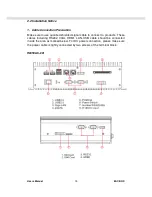
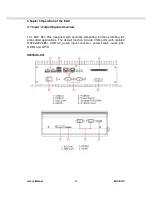
Power input (DC Version) 

Default  DC  terminal  block  power  source  input  compact  design  meets  the 
maritime  application.  The  terminal  block  is  to  be  secured  that  the  cable  to 
screw terminal.   
 

Serial ports for connection 

The  EAC  support  Rich  COM  ports  (including  isolated  RS232/422/485)  to 
satisfy the maritime accessories sensor units. Connect Standard D-SUB 9pin 
connector from accessory system to connect to the EAC to be a control center. 
 

HDMI port connection 

Use HDMI (Male) cable to connect to the display. 
 

LAN port connection 

The  Panel  PC  supports  one  10/100/1000  Mbps  Ethernet  interface  for 
connecting to the internet. 


USB port connection 

Use standard USB type A cable to connect any device that use USB interface 
for expansion functions. 


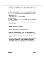
3.2 Starting the EAC & O/S Installation 


1.  Connect the EAC to Monitor through HDMI cable. 

2.  Connect the power to DC source and turn on the power switch. 

3.  Press “DEL” to enter the CMOS setting and check the BIOS setup. 

4.  You may install your own O/S if it is not installed. When installing O/S 

for this EAC, please use external equipment including Keyboard and 
Mouse and external USB CD/DVD-ROM to run the O/S and Driver 
setting. 

5.  To install the drivers, the EAC comes with a User’s Manual and Driver 

CD that contains most of the drivers and utilities of your needs. 
Following the step by step to install Driver (Please refer IS81 SBC 
User’s Manual Chapter 3, 4, 5, 6) include: Chipset, HDMI, Audio, and 
Ethernet. 


Summary of Contents for I330EAC-201

Page 1: ...Users Manual EAC BOX Embedded Automation Controller BOX USER MANUAL Version 1 4 IS81EAC 201 Intel QM67 Core i7 2655LE with 2 Isolated Serial Port Controller ...

Page 2: ...Users Manual EAC BOX REVISION HISTORY REVISION AUTHOR DATE DESCRIPTION 1 4 Jovi Hsu March 7 2013 IS81EAC 201 Copyright 2008 Winmate Communication INC ...

Page 3: ...ything to rest on the power cord Do not locate this product where persons will walk on the cord Never push objects of any kind into this product through cabinet slots as they may touch dangerous voltage points or short out parts that could result in a risk of fire or electric shock Never spill liquid of any kind on the product Do not attempt to service this product by yourself as opening or removi...

Page 4: ...ser Manual This manual you are reading 1 pc CD for System Driver Utility 1 pc AC to DC Adapter w Standard Power Cord for Power Supply Optional Accessories Item Description Note 1 pc of CD for Recovery CD for Operation System Windows 7 Embedded or Windows 7 Professional Embedded 1 pc of Windows 7 embedded or Windows 7 Professional Embedded Recovery Users Guide Optional with Windows 7 embedded or Wi...

Page 5: ...ES ABOUT THE EMBEDDED AUTOMATION CONTROLLER 6 1 2 BASIC CONSTRUCTION OF EAC 8 1 3 CERTIFICATE SERIAL NUMBER LABEL 9 CHAPTER 2 INSTALLATION 12 2 1 GENERAL INSTALLATION 12 2 2 INSTALLATION NOTICE 15 CHAPTER 3 OPERATION OF THE EAC 20 3 1 INPUT OUTPUT SIGNALS OVERVIEW 20 3 2 STARTING THE EAC O S INSTALLATION 21 ...

Page 6: ...Users Manual EAC BOX 5 CHAPTER 1 General Information ...

Page 7: ...Low Power CPU with Versatile Functions The EAC with Intel Core i7 3655LE QM67 Chipset that delivers the most performance per watt available in embedded computing systems It s a PC based system with DDR3 RAM HDMI port multi COM port interface and on board 10 100 1000 Mbps Ethernet USB port It is a compact design to meet the demanding performance requirements of most applications Wide Voltage Input ...

Page 8: ...lfilling any of customer s solution For different panel characteristics mechanical design and electronic component we can make it for you Approved EAC Winmate EAC designs are all followed IEC 60945 Maritime Navigation and Radio communication Equipment and Systems requirements The EAC series consist in different platform of industrial computing By testing for usability in a ship s wheelhouse during...

Page 9: ...tate of the art modulated technology can integrate all EAC components flexibly Figure 1 1 Basic Constructions Top Cover Bottom Cover Power Module Serial Module Back I O Cover Front I O Cover Storage Module Service Window Main Board Module Side Cover Side Cover ...

Page 10: ...C products are described as below 1 DNV Type Approval Model Label 2 No DNV Type Approval Model Label Power Rating and Input Voltage Compass Safety Distance Product Description Product and Serial Number Manufacturer and Country Input Voltage Product Description Product and Serial Number Manufacturer Country ...

Page 11: ... Box PC I330 EAC XXX SBC Board Platform Product Category Serial Number Serial Number Description 201 Std Package 202 w display extension 203 w PCI extension 204 w USB extension 205 w COM extension 206 w Fan extension ID3 w NM10 chipset IV3 w HM76 chipset ...

Page 12: ...Users Manual EAC BOX 11 CHAPTER 2 Installation ...

Page 13: ...g desktop wall mount 100x100 VESA mount with screws only 75x75 VEAS or DIN Rail with bracket For DIN Rail mount is normally for the industrial fields use it s easy to follow few steps to fix the display product in customer s fixture Check the mechanical and mounting concept as below first The fixture dimension and mounting holes based on drawing ...

Page 14: ...Users Manual EAC BOX 13 1 Align the EAC to the fixture on the back and screw by four M4 x 8 mm above bolts with nuts ...

Page 15: ...g kit using screw by four M4 x 8 mm above bolts with nuts by special request Non DNV approved 3 Optional Use two M4x 8mm bolts to drill through the DIN Rail mounting bracket into the mounting holes on the rear side of EAC 100x100 VEAS Non DNV approved ...

Page 16: ...o use qualified shielded signal cable to connect to products These cables including RS232 VGA HDMI LAN USB cable should be connected inside the area as marked below For DC power connection please make sure the power cable is tightly connected by two screws of the terminal block IS81EAC 201 ...

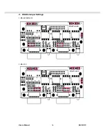
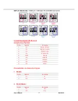
Page 17: ...Users Manual EAC BOX 16 2 RS232 Jumper Settings 1 RS 485 RS 422 2 RS 232 RS2T4 420 RS2T4 420 ...

Page 18: ...B9 Female Related connector DB9 Male Pin No Symbol Description 1 P1 DCD D TX RX 2 P2 RXD D TX RX 3 P3 TXD RX TX 4 P4 DTR RX TX 5 GND Ground 6 P6 DSR NC 7 P7 RTS NC 8 P8 CTS NC 9 P9 RI NC Pins definition of J3 and J8 of 3 types 1 RS 485 Pin No Symbol Description 1 P1 D 2 P2 D 2 RS 422 Master Pin No Symbol Description 1 P1 TX 2 P2 TX ...

Page 19: ...Users Manual EAC BOX 18 3 P3 RX 4 P4 RX 3 RS 422 Slave Pin No Symbol Description 1 P1 RX 2 P2 RX 3 P3 TX 4 P4 TX ...

Page 20: ...Users Manual EAC BOX 19 CHAPTER 3 Operation the EAC ...

Page 21: ...Output Signals Overview The EAC Box PCs designed with versatile computing functions fulfilling the embedded applications The default function include COM ports with isolated RS232 422 485 USB 3 0 power input connector power switch audio jack HDMI and GPIO IS81EAC 201 ...

Page 22: ...he internet USB port connection Use standard USB type A cable to connect any device that use USB interface for expansion functions 3 2 Starting the EAC O S Installation 1 Connect the EAC to Monitor through HDMI cable 2 Connect the power to DC source and turn on the power switch 3 Press DEL to enter the CMOS setting and check the BIOS setup 4 You may install your own O S if it is not installed When...

Reviews: