background image


G-WIN AMD Rugged Series Panel PC User Guide 

16 

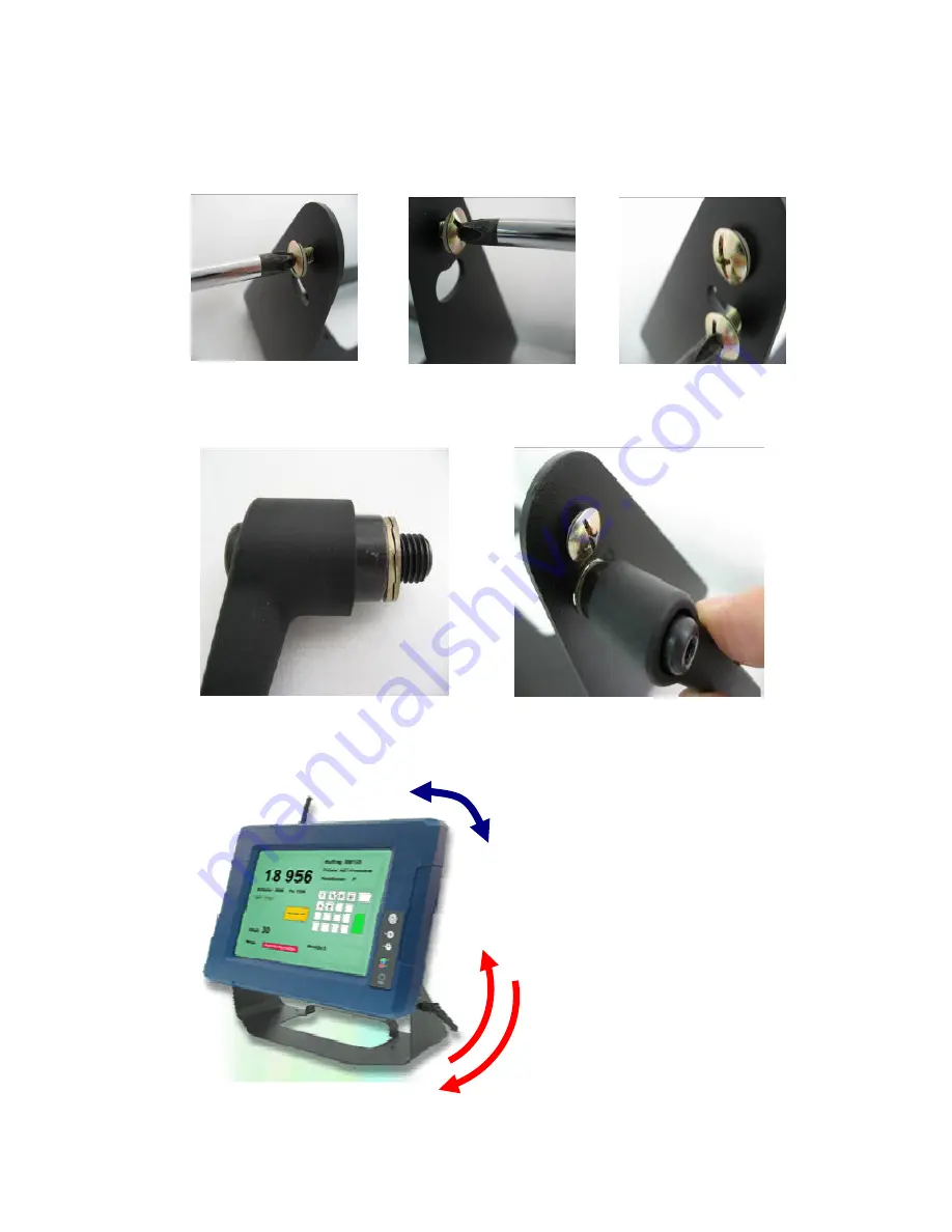
2.  Screw  on  three  normal  M5x10  screws  to fix  the  rugged  product  upon the 

stand. 


3.  Screw on Locking handle to screw the rugged product tight. 


4.  Loose the hand-screw adjustment tool, then you can adjust product angle 

on the stand. Then screw the product tight again to fix. 


Loose Locking handle 

Lock Locking handle 

Adjust the product angle 

Summary of Contents for G-WIN AMD Rugged Series

Page 1: ...G WIN AMD Rugged Series Panel PC AMD Geode LX800 3 5 SBC Ultra Low Power Fanless Design with CPU TFT LCD and 10 100 1000 base T Ethernet User Guide Version 1 1...

Page 2: ...mits are designed to provide reasonable protection against harmful interference when the equipment is operated in a commercial environment This equipment uses and can radiate radio frequency energy if...

Page 3: ...ht infringement unless otherwise specified Applications that are described in this manual are for illustration purposes only Winmate Communication Inc makes no representation or warranty that such app...

Page 4: ...website at http www winmate com to find the update information about the product Second contact with your distributor sales representative or our customer service center for technical support if you n...

Page 5: ...can be damaged by sudden power surges Only experienced electronics personnel should open the PC chassis Caution Always ground yourself to remove any static charge before touching the CPU card Modern...

Page 6: ...r cord so that people cannot step on it Do not place anything over the power cord 10 All cautions and warnings on the equipment should be noted 11 If the equipment is not used for a long time disconne...

Page 7: ...G WIN AMD Rugged Series Panel PC User Guide VII Revision History Version Date Note Author 1 0 2008 01 25 First Version Martin Chen 1 1 2008 07 15 Second Version Sarah Su...

Page 8: ...ut Output Devices 5 2 2 Starting the Panel PC O S Installation 6 2 3 Driver Installation 6 CHAPTER 3 TOUCH DRIVER INSTALLATION 7 3 1 Introduction 7 3 2 The ELO AccuTouch CarrollTouch infrared Driver I...

Page 9: ...gn sunlight readable panel WLAN integration great ability for anti shock vibration IP65 protection and anti corrosion coating with aluminum alloy housing Both of great mobility and robust design are f...

Page 10: ...Chipset 10 100 Mbps Optional Dual Realtek 8110cs Giga bit Ethernet Audio Realtek ALC203 AC97 Chipset AC97 codec SATA Build in SATA connector supports 2 SATA1 0 ports Serial 4x RS 232 4 x pin header US...

Page 11: ...Resolution Recommended Display Color R08A83S VMT1 800 600 262 144 6bit colors R08A83S VMM1 640 480 262 144 6bit colors R08A83S VMM2 1024 768 262 144 6bit colors R08A83S VMU1 800 600 262 144 6bit colo...

Page 12: ...ut normally comes with use wide power range module inside 3 DC Lockable Input Default Connect the power cord to the AC outlet and connect the power to the monitor through the AC DC adapter 4 PS 2 PS 2...

Page 13: ...ional 9 pin male Serial Port connector that can attach a serial mouse or other serial devices directly to the port 5 DC Lockable Input Default Connect the power cord to the AC outlet and connect the p...

Page 14: ...the steps and use external equipment as Keyboard and Mouse a Please use external USB DVD ROM to run the O S and Driver setting as picture showed below 2 3 Driver Installation The PPC comes with a Use...

Page 15: ...sistive technology The touch screen may be a flat spherical or cylindrical It is installed over the face of the display Since its shape matches of the display face the touch screen has excellent clari...

Page 16: ...elotouch com Support dnld asp for a complete list of available drivers For Driver Installation please install the ELO Touch System Touch Tools CD for Windows XP Windows 2000 Windows Me Windows 98 Win...

Page 17: ...9 3 2 1 Configuration Utility After finishing the installation please follow the steps to test the configuration utility Step 1 Enter My Computer click the ELO Touch Screen shortcut function Step 2 C...

Page 18: ...ged Series Panel PC User Guide 10 Step 3 Correct 4 point locations on screen with the Panel PC Screen display as follows Step 4 Touch the yes function if the cursor follows your finger and finish the...

Page 19: ...iguration support The calibration and draw test of touch panel are done by this utility Besides users can add or remove for new RS 232 or PS 2 touch panel devices 3 3 1 Install Touch Kit Follow below...

Page 20: ...nishing the installation please follow the steps to test the configuration utility Step 1 Click the Touch Kit shortcut function in the desktop Step 2 Enter General function and choose the language you...

Page 21: ...Rugged Series Panel PC User Guide 13 Step 3 Correct 4 point locations on screen with the Panel Screen display as following Step 4 Play Yes to continue if 4 points calibration test is fine and finish t...

Page 22: ...y kind of mounting approaches There are two main mounting approaches as Vehicle mounting and VESA mounting both approaches are very easy for user to set up the Panel PC As the pictures guided VEHICLE...

Page 23: ...ck the complete items with nothing missing as following Rugged Panel PC bracket accessory list One Bracket Stand Three M5x10 screws with washer One Locking handle adjustment tool with metal washer SOP...

Page 24: ...x the rugged product upon the stand 3 Screw on Locking handle to screw the rugged product tight 4 Loose the hand screw adjustment tool then you can adjust product angle on the stand Then screw the pro...

Page 25: ...Series Panel PC User Guide 17 4 2 VESA Mounting Fix the Panel PC with four screws standard VESA and fasten on the wall with other four screws 75 mm x 75 mm VESA mount Holes 75 mm Touch 3mm 6mm Panel...

Page 26: ...ended equal to the CMOS setting for panel Flat Panel Type If the external display is lower resolution than CMOS setting in Windows it may cause display indistinct Recommendation in CMOS setting i Choo...

Page 27: ...e Package 2 2 The VGA output port for A831 is only for displaying the same images as built in display The extended mode is not available for A831 3 When you use CF card as storage of Operation System...

Reviews: