background image

User Manual of Network Speed Dome 

53


Figure 6-20


Parent Directory 


Child  directory

:  It  is  a  sub-folder  which  can  be  created  in  the  parent 

directory. The files will be saved in a sub-folder in FTP server. The name of 
folder can be defined as shown in following Figure 6-21. 


Figure 6-21


Child Directory 


Upload type: 

To enable uploading the captured picture to the FTP server. 

3.


Click 

  to save the settings. 


If you want to upload the captured pictures to FTP server, you also have to enable 

the  continuous  snapshot  or  event-triggered  snapshot  in 

Snapshot

  interface.  For  detailed 

information, please refer to the Section


7.3 Configuring Snapshot Settings


6.3.9


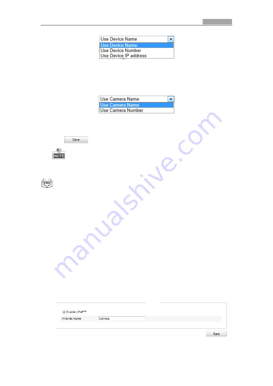
Configuring UPnP™ Settings 

Universal  Plug  and  Play  (UPnP™)  is  a  networking  architecture  that  provides 
compatibility  among  networking  equipment,  software  and  other  hardware  devices. 
The  UPnP  protocol  allows  devices  to  connect  seamlessly  and  to  simplify  the 
implementation of networks in the house and corporate environments. 
With the  function  enabled,  you  don’t need  to  configure the port  mapping for each 
port, and the camera is connected to the Wide Area Network via the router. 

Steps: 

1.


Enter the UPnP™ settings interface. 

Configuration >Advanced Configuration >


Network > UPnP 

2.


Check the checkbox to enable the UPnP™ function. 
You can edit the Friendly Name of the speed dome. This name can be detected 
by corresponding device, such as a router. 


Figure 6-22


Configure UPnP Settings 

Summary of Contents for RED LINE CT-NP302-IR

Page 1: ...Network Speed Dome User Manual V5 1 0...

Page 2: ...ll readily improve or update the products or procedures described in the manual DISCLAIMER STATEMENT Underwriters Laboratories Inc UL has not tested the performance or reliability of the security or s...

Page 3: ...nce received including interference that may cause undesired operation EU Conformity Statement This product and if applicable the supplied accessories too are marked with CE and comply therefore with...

Page 4: ...age SELV standard The power consumption cannot be less than the required value Do not connect several devices to one power adapter as an adapter overload may cause over heating and can be a fire hazar...

Page 5: ...the sensor not be exposed to the laser beam For working temperature please refer to the specification manual for details To avoid heat accumulation good ventilation is required for a proper operating...

Page 6: ...MANUALLY 22 4 4 OPERATING PTZ CONTROL 22 4 4 1 PTZ Control Panel 22 4 4 2 Setting Calling a Preset 23 4 4 3 Setting Calling a Patrol 25 4 4 4 Setting Calling a Pattern 27 4 5 CONFIGURING LIVE VIEW PA...

Page 7: ...Settings 67 6 6 CONFIGURING AND HANDLING ALARMS 68 6 6 1 Configuring Motion Detection 68 6 6 2 Configuring Video Tampering Alarm 72 6 6 3 Handling Exception 73 CHAPTER 7 RECORD SETTINGS 75 7 1 CONFIGU...

Page 8: ...auto scan tilt scan frame scan random scan and panorama scan Presets A preset is a predefined image position When the preset is called the dome will automatically move to the defined position The pres...

Page 9: ...t mode and deliver black and white images with high quality Slow Shutter In slow shutter mode the shutter speed will automatically slow down in low illumination conditions to maintain clear video imag...

Page 10: ...to scan random scan patrol 1 8 pattern 1 4 preset 1 8 frame scan panorama scan tilt scan day night reboot PT adjust Aux Output etc Park Action This feature allows the dome to start a predefined action...

Page 11: ...via a LAN you need to connect the network speed dome in the same subnet with your computer and install the SADP or client software to search and change the IP of the network speed dome For the detail...

Page 12: ...in Figure 2 3 Use the client software to list the online devices Please refer to the user manual of client software for detailed information 2 Change the IP address and subnet mask to the same subnet...

Page 13: ...ectly Connecting the network speed dome via a router Steps 1 Connect the network speed dome to the router 2 Assign a LAN IP address the subnet mask and the gateway Refer to Section 2 1 2 Detecting and...

Page 14: ...network speed dome to a modem or a router Connecting the network speed dome via a router Steps 1 Connect the network speed dome to the router 2 In the speed dome assign a LAN IP address the subnet mas...

Page 15: ...s is dynamically assigned via PPPoE so the IP address always changes after rebooting the speed dome To solve the inconvenience of the dynamic IP you need to get a domain name from the DDNS provider E...

Page 16: ...tion Steps 1 Install and run the IP Server software in a computer with a static IP 2 Access the network speed dome through the LAN with a web browser or the client software 3 Enable DDNS and select IP...

Page 17: ...g 192 0 0 64 and press the Enter key to enter the login interface 3 Select English as the interface language on the top right of login interface 4 Input the user name and password and click The defau...

Page 18: ...User Manual of Network Speed Dome 17 Figure 3 2 Download and Install Plug in Figure 3 3 Install Plug in 2 Figure 3 4 Install Plug in 3...

Page 19: ...User Manual of Network Speed Dome 18 You may have to close the web browser to install the plug in Please reopen the web browser and log in again after installing the plug in...

Page 20: ...Purpose The live video page allows you to view live video capture images realize PTZ control set call presets and configure video parameters Log in the network speed dome to enter the live view page o...

Page 21: ...ning tilting focusing and zooming actions of the speed dome The lighter wiper one touch focus and lens initialization control Preset patrol pattern Set and call the preset patrol pattern for the speed...

Page 22: ...eo Audio referring to Section 6 4 1 Configuring Video Settings Full screen Mode You can double click on the live video to switch the current live view into full screen or return to normal mode from th...

Page 23: ...turing Pictures Manually In the live view interface click on the toolbar to capture the live pictures or click to record the live video The local saving paths of the captured pictures and clips can be...

Page 24: ...rpose A preset is a predefined image position For the defined preset you can click the calling button to quickly view the desired image position Setting a Preset Steps 1 In the PTZ control panel selec...

Page 25: ...Select any preset from the list 2 Click the preset number you need on the keyboard The following presets are predefined with special commands You can only call them but not configure them For instance...

Page 26: ...preset 1 to 32 Before you enable this function please set the preset 1 to 32 first 4 4 3 Setting Calling a Patrol Purpose A patrol is a memorized series of preset function It can be configured and cal...

Page 27: ...dome moves to another patrol point after the patrol time Patrol Speed It is the speed of moving from one preset to another 5 Click to save a preset into the patrol 6 Repeat the steps from 3 to 5 to a...

Page 28: ...ace There are up to 4 patterns for customizing Setting a Pattern Steps 1 In the PTZ control panel click to enter the pattern settings interface 2 Select a pattern number from the list as shown in Figu...

Page 29: ...ling the pattern proportional pan is valid the limit stops and auto flip will be invalid and the 3D positioning operation is not supported 4 5 Configuring Live View Parameters Main stream Sub stream Y...

Page 30: ...User Manual of Network Speed Dome 29 You can scale up down the live view image by clicking the image size can be 4 3 16 9 original or auto...

Page 31: ...ps 1 Enter the Initial Position Configuration interface Configuration Advanced Configuration PTZ Initial Position Figure 5 1 PTZ Configuration 2 Click the PTZ control buttons to find a position as the...

Page 32: ...d Proportional Pan If you enable this function the pan tilt speeds change according to the amount of zoom When there is a large amount of zoom the pan tilt speed will be slower for keeping the image f...

Page 33: ...Always Open Preset Status Set the preset name display duration while calling the preset as 2 seconds 5 seconds 10 seconds Always Close or Always Open Power off Memory The dome can resume its previous...

Page 34: ...ed only in the limited surveillance area Manual Stops of Limit Type is prior to Scan Stops When you set these two limit types at the same time Manual Stops is valid and Scan Stops is invalid 3 Click t...

Page 35: ...duled Tasks Figure 5 4 Configure Scheduled Tasks 2 Check the checkbox of Enable Scheduled Task 3 Set the Park Time You can set the park time a period of inactivity before the dome starts the scheduled...

Page 36: ...hedule as all day or click Customize and input the Start Time and End Time for each task and click Enter on your keyboard to enter the time 4 Choose the task type from the drop down list You can choos...

Page 37: ...k time Scheduled Tasks function is prior to Park Action function When these two functions are set at the same time only the Scheduled Tasks function takes effect Steps 1 Enter the Park Action Settings...

Page 38: ...Figure 5 9 Draw the Privacy Mask 2 Click the PTZ control buttons to find the area you want to set the privacy mask 3 Click click and drag the mouse in the live video window to draw the area 4 You can...

Page 39: ...5 7 Clearing PTZ Configurations Purpose You can clear PTZ configurations in this interface including all presets patrols patterns privacy masks PTZ limits and scheduled tasks Steps 1 Enter the Clearin...

Page 40: ...6 1 Local Configuration Interface 2 Configure the following settings Live View Parameters Set the protocol type stream type image size and live view performance Protocol Type TCP UDP MULTICAST and HT...

Page 41: ...nloaded video files The size can be set to 256M 512M or 1G Save record files to Set the saving path for the manually recorded video files Save downloaded files to Set the saving path for the downloade...

Page 42: ...Settings Configuring Time Synchronization by NTP Server Steps 1 Check the radio button to enable the NTP function 2 Configure the following settings Server Address IP address of NTP server NTP Port P...

Page 43: ...eck the Sync with local time checkbox to synchronize the time of the speed dome with the time of your computer Figure 6 4 Time Sync Manually Select the Time Zone Purpose When the speed dome is taken t...

Page 44: ...dvanced Configuration System DST 2 Check to enable the DST function 3 Set the date of the DST period 4 Click to save the settings Figure 6 6 DST Settings 6 3 Configuring Network Settings 6 3 1 Configu...

Page 45: ...Transmission Unit MTU is 500 1500 The default value is 1500 The Multicast sends a stream to the multicast group address and allows multiple clients to acquire the stream at the same time by requestin...

Page 46: ...e Configuration Basic Configuration Network Port Or Configuration Advanced Configuration Network Port Figure 6 9 Port Settings 2 Set the HTTP port RTSP port and port of the speed dome HTTP Port The de...

Page 47: ...d Password should be assigned by your ISP 4 Click to save and exit the interface 6 3 4 Configuring DDNS Settings Purpose If your speed dome is set to use PPPoE as its default network connection you ca...

Page 48: ...DNS DynDNS Steps 1 Enter Server Address of DynDNS e g members dyndns org 2 In the Domain text field enter the domain name obtained from the DynDNS website 3 Enter the Port of DynDNS server 4 Enter the...

Page 49: ...n is the same with the device alias in the SIMPLEDDNS server 3 Click to save the settings Figure 6 14 SIMPLEDDNS Settings NO IP Steps 1 Enter Server Address of NO IP 2 In the Domain text field enter t...

Page 50: ...n you select should be the same as that of the SNMP software Steps 1 Enter the SNMP Settings interface Configuration Advanced Configuration Network SNMP Figure 6 15 SNMP Settings 2 Check the correspon...

Page 51: ...s shown as follows Network Switch PC PC RADIUS Server Network Dome Net Figure 6 16 Protected LAN Before connecting the Network Camera to the protected LAN please apply a digital certificate from a Cer...

Page 52: ...sion must be identical with that of the router or the switch 5 Enter the user name and password issued by the CA to access the server 6 Click to finish the settings The camera reboots when you save th...

Page 53: ...er and configure the following parameters for uploading captured pictures Steps 1 Enter the FTP Settings interface Configuration Advanced Configuration Network FTP Figure 6 19 FTP Settings 2 Configure...

Page 54: ...7 3 Configuring Snapshot Settings 6 3 9 Configuring UPnP Settings Universal Plug and Play UPnP is a networking architecture that provides compatibility among networking equipment software and other h...

Page 55: ...lick to save the settings 6 3 11Configuring Email Settings Purpose The system can be configured to send an Email notification to all designated receivers if an alarm event is detected e g motion detec...

Page 56: ...SMTP Server IP address or host name e g smtp 263xmail com SMTP Port The SMTP port The default TCP IP port for SMTP is 25 Enable SSL Check the checkbox to enable SSL if it is required by the SMTP serv...

Page 57: ...kbox to use authentication to log in to this server and enter the login user name and password Receiver Select the receiver to which the email is sent Up to 2 receivers can be configured Receiver The...

Page 58: ...idth and the sub stream can be used for live viewing when the bandwidth is limited Refer to the Section 6 1 Configuring Local Parameters for switching the main stream and sub stream for live viewing 3...

Page 59: ...r MJPEG I Frame Interval Set the I Frame interval from 2 to 250 4 Click to save the settings 6 4 2 Configuring Audio Settings Steps 1 Enter the Audio Settings interface Configuration Basic Configurati...

Page 60: ...s Fixed Region The fixed region encoding is the ROI encoding for the manually configured area And you can choose the Image Quality Enhancing level for ROI encoding and you can also name the ROI area S...

Page 61: ...parameters in Display Settings interface vary depending on the models of speed dome You can double click the live view to enter full screen mode and double click it again to exit Steps 1 Enter the Dis...

Page 62: ...Settings Exposure Mode The Exposure Mode can be set to Auto Iris Priority Shutter Priority Manual Auto The iris shutter and gain values will be adjusted automatically according to the brightness of t...

Page 63: ...nd High Figure 6 31 Slow Shutter Focus Settings Focus Mode The Focus Mode can be set to Auto Manual Semi auto Auto The speed dome focuses automatically at any time according to objects in the scene Se...

Page 64: ...ed domes support IR Light Mode When the IR Light Mode is auto the day night mode is adjusted automatically according to the IR Light Mode Manually setting the day night mode is invalid When the IR Lig...

Page 65: ...ce automatically according to the current color temperature Manual White Balance In MWB mode you can adjust the color temperature manually to meet your own demand as shown in Figure 6 34 Figure 6 34 M...

Page 66: ...OFF or CENTER This function varies depending on the models of speed dome Video Standard You can set the Video Standard to 50hz PAL or 60hz NTSC according to the video system in your country This funct...

Page 67: ...tilt position Time Supports for time display Preset Title Identifies preset being called Camera Name Identifies the name of speed dome You can customize the on screen display of time Steps 1 Enter the...

Page 68: ...mize the text overlay Steps 1 Enter the Text Overlay Settings interface Configuration Advanced Configuration Image Text Overlay 2 Check the checkbox in front of textbox to enable the on screen display...

Page 69: ...illance Center Send Email Trigger Alarm Output etc For example when an external alarm is triggered the network speed dome sends a notification to an e mail address 6 6 1 Configuring Motion Detection P...

Page 70: ...a motion detection area You can draw up to 8 motion detection areas on the same image 4 Click to finish drawing You can click to clear all of the areas 5 Move the slider to set the sensitivity of the...

Page 71: ...ing schedule as shown in Figure 6 41 3 Click to set the time period for the arming schedule 4 After you set the arming schedule you can click to copy the schedule to other days Optional 5 Click to sav...

Page 72: ...ure the different types of linkage method Figure 6 42 Linkage Method Check the checkbox to select the linkage method Notify surveillance center send email upload to FTP trigger channel and trigger ala...

Page 73: ...occurs You have to set the recording schedule to realize this function Please refer to Section 7 2 Configuring Recording Schedule for settings the recording schedule Trigger Alarm Output Trigger one o...

Page 74: ...hedule for motion detection Refer to Step 2 Set the Arming Schedule for Motion Detection in Section 6 6 1 Configuring Motion Detection 5 Check the checkbox to select the linkage method taken for the t...

Page 75: ...ation Advanced Configuration Events Exception 2 Check the checkbox to set the actions taken for the Exception alarm Refer to Step 3 Set the Alarm Actions Taken for Motion Detection in Section 6 6 1 Co...

Page 76: ...on Advanced Configuration Storage NAS 2 Select the NAS type as NFS or SMB CIFS If you select SMB CIFS you need to enter the User Name and Password Figure 7 1 Select NAS Type 3 Enter the IP address of...

Page 77: ...ion completed the status of disk will become Normal as shown in Figure 7 5 Figure 7 5 View Disk Status Up to 8 NAS disks can be connected to the speed dome To initialize and use the SD card after inse...

Page 78: ...e record The time you set to start recording before the scheduled time or the event For example if an alarm triggers recording at 10 00 and the pre record time is set as 5 seconds the speed dome start...

Page 79: ...cord Schedule 5 Choose the day to set the record schedule 1 Set all day record or segment record If you want to configure the all day recording please check the All Day checkbox If you want to record...

Page 80: ...check the checkbox of Trigger Channel in the Linkage Method of Alarm Input Settings interface For detailed information please refer to Section 6 6 4 Configuring External Alarm Input Record Triggered b...

Page 81: ...s Steps 1 Enter the Snapshot Settings interface Configuration Advanced Configuration Storage Snapshot 2 Check the Enable Timing Snapshot checkbox to enable continuous snapshot Check the Enable Event t...

Page 82: ...to Section 6 3 8 Configuring FTP Settings for more details to configure FTP parameters 2 Check checkbox in Motion Detection Settings or Alarm Input interface Please refer to Step 3 Set the Alarm Acti...

Page 83: ...on explains how to view the remotely recorded video files stored in the network disks or SD cards Task 1 To play back the video files Steps 1 Click on the menu bar to enter playback interface Figure 8...

Page 84: ...volume Mute Speed down Download video files Speed up Download captured pictures Display playback status Playback by frame You can choose the file paths locally for downloaded playback video files and...

Page 85: ...hown in Figure 8 7 2 Set the start time and end time Click Search The corresponding video files are listed on the left Figure 8 7 Video Downloading interface 3 Check the checkbox in front of the video...

Page 86: ...enu is shown in Figure 8 8 2 Set the linkage type of capturing the pictures as timing alarm motion etc 3 Set the start time and end time Click Search The corresponding picture files are listed on the...

Page 87: ...configure network storage for the speed dome or insert a SD card in the speed dome Steps 1 Click on the menu bar to enter log searching interface Figure 9 1 Log Searching Interface 2 Set the log sear...

Page 88: ...User Manual of Network Speed Dome 87 4 To export the log files click to save the log files in your computer...

Page 89: ...modify or delete other accounts Up to 32 user accounts can be created Figure 10 1 User Information Add a User Steps 1 Click to add a user 2 Input the new User Name select Level and input Password The...

Page 90: ...Modify a User Steps 1 Left click to select the user from the list and click 2 Modify the User Name Level or Password 3 In the Basic Permission field and Camera Configuration field you can check or unc...

Page 91: ...al of Network Speed Dome 90 Figure 10 3 Modify a User Delete a User Steps 1 Left click the user name you want to delete and click 2 Click on the pop up dialogue box to delete the user Figure 10 4 Dele...

Page 92: ...ication Figure 10 5 RTSP Authentication 2 Select the Authentication type basic or disable in the drop down list to enable or disable the RTSP authentication 3 Click to save the settings 10 3Configurin...

Page 93: ...interface to log in Allowed Allow only the IP addresses added in the IP Address Filter interface to log in Figure 10 8 IP Address Filter 10 5Viewing Device Information Enter the Device Information int...

Page 94: ...u It is the reference for maintenance or modification in future Figure 10 9 Device Information 10 6Maintenance 10 6 1Rebooting the Speed Dome Steps 1 Enter the Maintenance interface Configuration Basi...

Page 95: ...tton with caution Figure 10 11 Restore Default Settings 10 6 3Importing Exporting Configuration File Steps 1 Enter the Maintenance interface Configuration Basic Configuration System Maintenance Or Con...

Page 96: ...aintenance Or Configuration Advanced Configuration System Maintenance 2 Click to select the local upgrade file and then click to start remote upgrade The upgrading process will take 1 to 10 minutes Pl...

Page 97: ...fter launch the SADP software it automatically searches the online devices every 15 seconds from the subnet where your computer locates It displays the total number and information of the searched dev...

Page 98: ...e will be displayed in the Modify Network Parameters panel on the right side 2 Edit the modifiable network parameters e g IP address and port number 3 Enter the password of the admin account of the de...

Page 99: ...e A 2 1 Select the WAN Connection Type 2 Set the LAN parameters of the router as in the following figure including IP address and subnet mask settings Figure A 2 2 Set the LAN parameters 3 Set the por...

Page 100: ...he ports of another speed dome as 81 8001 8201 8211 and 555 with IP 192 168 1 24 Refer to the steps as below Steps 1 As the settings mentioned above forward the port 80 8000 8200 8210 and 554 for the...

Reviews: