MAINTENANCE AND SERVICE 18
PUMP; the hydraulic pump is driven directly from the crankshaft of
the engine.
FILTER; the suction strainer filter is located in the base of the tank
as described above, hydraulic is drawn from the tank through the
strainer to the pump.
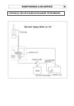
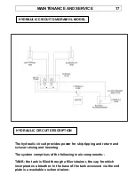
TIPPING/SCISSOR CONTROL VALVE; the control valve receives oil
from the pump and when the outer operating lever is activated
delivers oil to the tipping ram, when the inner lever is activated the
valve delivers oil to the scissor ram. When the levers are in the
neutral position the control valve directs the hydraulic oil back to
the tank. The rate of oil flow to the tipping or scissor ram is directly
proportional to the distance that the operating lever is moved from
the neutral position. The control valve contains a safety device in
the form of a preset relief valve. If the operating levers are held fully
in either the ‘dump’ or ‘return’ or scissor ‘raise’ or ‘lower’ position
the relief valve will ‘blow off’ when the ram reaches the end of its
travel diverting oil back to the tank. This prevents excessive
pressure from damaging the hydraulic pump and other components.
TIPPING RAM; the single tipping ram is of the double acting type, oil
enters the lower part of the cylinder (full bore) when the operating
lever is moved forwards and pushes the piston and rod out of the
cylinder tipping the skip. When the lever is moved to the rear oil
enters the upper part of the cylinder (annulus) and pushes the
piston and rod into the cylinder lowering the skip. Oil displaced from
the opposite part of the cylinder as the piston and rod move in or
out is returned to the tank via the control valve.
SCISSOR RAM; the single scissor ram is of the double acting type,
oil enters the lower part of the cylinder (full bore) when the operating
lever is moved forwards and pushes the piston and rod out of the
cylinder raising the scissors. When the lever is moved to the rear oil
enters the upper part of the cylinder (annulus) and pushes the
piston and rod into the cylinder lowering the scissors. Oil displaced
from the opposite part of the cylinder as the piston and rod move in
or out is returned to the tank via the control valve.
Note; Only qualified experienced personnel should attempt to carry
out anything other than the basic checks, unless you have the
HYDRAULIC SYSTEM CHECKS
Summary of Contents for TD500
Page 2: ......
Page 4: ......
Page 29: ...PARTS INFORMATION 23 TD500 TD500HL PARTS SECTION ...
Page 30: ......
Page 32: ......
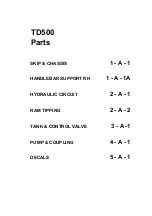
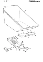
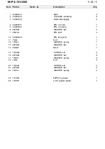
Page 33: ...1 A 1 TD500 Dumper ...
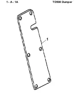
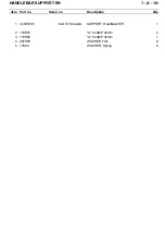
Page 35: ...1 A 1A TD500 Dumper ...
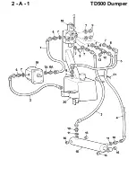
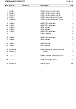
Page 37: ...2 A 1 TD500 Dumper ...
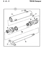
Page 39: ...2 A 2 TD500 Dumper ...
Page 41: ...3 A 1 TD500 Dumper ...
Page 43: ...4 A 1 TD500 Dumper ...
Page 45: ...5 A 1 TD500 Dumper ...
Page 48: ......
Page 49: ...1 A 1 TD500HL Dumper ...
Page 51: ...1 A 1A TD500HL Dumper ...
Page 53: ...1 A 2 TD500HL Dumper ...
Page 55: ...2 A 1 TD500HL Dumper ...
Page 57: ...2 B 1 TD500HL Dumper ...
Page 59: ...2 C 1 TD500HL Dumper ...
Page 61: ...2 R 1 TD500HL Dumper ...
Page 63: ...3 A 1 TD500HL Dumper ...
Page 65: ...4 A 1 TD500HL Dumper ...
Page 67: ...4 A 2 TD500HL Dumper 5 6 ...

