Winegard RoadTrip LP-1000 Installation & Operation Manual Download Page 4

4

1.  INTRODUCTION

1.1 System Overview

The Winegard RoadTrip LP is a low profile, in-motion satellite system.
RoadTrip LP utilizes GPS (global positioning system) and DVB (digital
video broadcasting) technology. GPS is used to determine the present
location of your antenna, and DVB is used to verify the antenna has
located the correct satellite.

Roadtrip is a Ku-band satellite television reception antenna that
is gyro stabilized and has a continuous 360° rotation to keep it
locked on the selected satellite. RoadTrip is designed for both
open-road tracking and stationary operation.

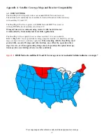
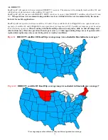
The RoadTrip system has certain operational limits with

respect to use in the United States. Although designed for use with
DISH Network and DIRECTV, t

he system may not work in all

geographical locations or with all satellite receivers

See coverage

maps,  pages 14 and 15.

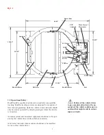
1.2  Parts Provided with RoadTrip LP

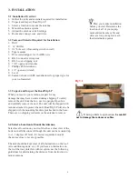
1. Antenna System (includes antenna, LNB, baseplate and control electronics) Fig 1.1
2. Radome
3. Mounting Bracket (4)
4. 35 ft. RG-6 coax with weather-protected male F-connector
5. 35 ft 2-conduct 16 AWG power wire with weather-protected connector
6. Hardware Kit (See Section 3.5 for contents)
7. Installation/Operation Manual

See page five for diagram of interior and parts

1.3  Additional Equipment and Materials Required for Operation of
       RoadTrip LP

1. Television or Video Monitor
2. Satellite Receiver with authorized programming
3.    Approved sealant for roof

Please refer to

appendix A


for satellite

coverage maps and infor-
mation on receiver
compatability.

2.  SAFETY

2.1 Installation Safety:

Winegard highly recommends the RoadTrip LP antenna system be
installed by a professional installer who is familiar with satellite antenna
technology and recreational vehicle wiring.

Do not attempt to install this system in the rain. Sensitive electronics
may be exposed and water may also enter vehicle. Before drilling any holes for
installation, make sure thre are no obstructions, such as wiring, etc.

Read the entire manual before attempting to install the antenna
system. Follow the instructions carefully when you begin.

Use all appropriate safety equipment, including eye protection, when
installing this system.

Do not attempt to

install the antenna system
by yourself. Two or more
people are required to lift
the antenna onto the roof.

Winegard is not

liable for damage,
expenses, or injury caused
by improper installation.

Summary of Contents for RoadTrip LP-1000

Page 1: ... St Burlington IA 52601 2000 319 754 0600 FAX 319 754 0787 www winegard com Printed in U S A Winegard Company 2004 2005 2452040 Rev 12 19 05 INSTALLATION OPERATION MANUAL SATELLITE SYSTEM MODEL LP 1000 Made in U S A U S Patent Pending ...

Page 2: ...e products or services Congratulations You have selected one of the most advanced and lowest profile satellite antennas available today The Winegard RoadTrip LP antenna is a technologically advanced satellite tracking system The RoadTrip LP is designed for use with DIRECTV and DISH Network satellite television providers This manual provides important information on the installation and operation o...

Page 3: ...unt the Antenna 6 7 3 5 Mounting the Antenna 8 3 6 Adjusting Antenna Switch Settings 9 3 7 Install and Connect Cables and Wiring 10 11 4 Operation 12 4 1 Initial Satellite Receiver Setup 12 4 2 Stationary Operation of RoadTrip LP 12 4 3 Tracking with RoadTrip LP 13 4 4 Satellite Signal Interruption 13 Appendix A Satellite Coverage Maps and Receiver Compatability A 1 DISH Network 14 A 2 DIRECTV 15 ...

Page 4: ...th weather protected connector 6 Hardware Kit See Section 3 5 for contents 7 Installation Operation Manual See page five for diagram of interior and parts 1 3 Additional Equipment and Materials Required for Operation of RoadTrip LP 1 Television or Video Monitor 2 Satellite Receiver with authorized programming 3 Approved sealant for roof Please refer to appendix A for satellite coverage maps and in...

Page 5: ...pment should never be oper ated by the vehicle driver while vehicle is in motion Active television and video monitors should never be installed in view of the vehicle driver Failure of the vehicle driver to pay complete attention to the op eration of the vehicle could cause an accident that might result in serious injury or death Fig 1 1 40 00 33 250 33 500 28 625 28 625 Base Back Reflector Reflec...

Page 6: ...people Open box and carefully remove the unit The unit will be shipped with radome attached to protect the unit RoadTrip LP will also be shipped with the mounting brackets preattached to the base There are no shipping restraints on the antenna to remove 3 4 Select a Location to Mount the Antenna Select level location on your roof that has a clear view of the horizon in all directions Although the ...

Page 7: ...e cables and wiring exiting the rear driver s side of the antenna Option B Mount the antenna pointing directly towards the back of the vehicle with the cables and wiring exiting the front passenger s side of the antenna Refer to the following drawings of Option A and Option B Fig 3 3 Fig 3 3 1 Option A Option B FRONT OF VEHICLE FRONT OF VEHICLE BACK OF VEHICLE BACK OF VEHICLE The mounting option w...

Page 8: ... place in permanent location Using a level adjust the leveling screws by tightening or loosening the flange nut under the baseplate mounting foot Fig 3 4 Remove locknut from foot Fig 3 4 Lift up baseplate slide foot out and apply sealant to bottom of foot Slide back into place and tighten locknut Screw down brackets attached to antenna using 4 10 screws for each bracket After all mounting brackets...

Page 9: ...er and the mounting option selected it may be necessary to remove the antenna radome and adjust the switch setting The antenna switch comes preset at the factory for mounting Option A see Section 3 4 Fig 3 3 and for use with DirecTV receivers see Fig 3 5 If you have selected mounting Option B or if you are using a DISH network receiver remove the antenna radome and adjust the switch setting on top...

Page 10: ...ector on the 35 section of wire The power connector is directional Align wire colors and firmly push connector together until latch snaps and secures Fig 3 8 All coax connections must be finger tightened then given 1 4 turn with a 7 16 wrench 3 7 Route and connect the coax and wires Determine the best location for the RG 6 coax and 16 gauge power wires to enter the vehicle and the location of the ...

Page 11: ...le Place the cable entry plate over the hole and cables Screw in place and seal plate and screws with the approved sealant Depending on the length of the coax and wiring on the roof it may be necessary to secure them with cable clamps Clamping the cable every 12 to 16 should eliminate any unecessary cable movement Fig 3 9 Fig 3 10 Connect the ground wire from the vehicle 12 VDC power source and th...

Page 12: ...power switch and wait for satellite acquisition On intial setups it may be necessary to set up your receiver for multidish operation if required after the unit has acquired the satellite and entered sleep mode Refer to Appendix B for information on multidish setups for your satellite provider How the RoadTrip Works During Stationary Satellite Acquisition The reflector on the antenna will rotate cl...

Page 13: ...e to actively track the satellite for up to 6 minutes If the vehicle is stationary for more than 6 minutes the unit will go into sleep mode stop actively tracking the satellite and end the conical search 4 4 Satellite Signal Interruption Satellite TV reception systems may be disrupted by weather condi tions Satellite signals may be lost temporarily during a steady rainfall Rain snow or dew on the ...

Page 14: ...e manufactuer for mobile applications The RoadTrip will not operate in areas where satellite 119 is not avaliable Refer to Fig A 1 1 for an operational coverage map for satellite 119 Satellite coverage maps are based on level stationary operation When tracking with the RoadTrip road grades hills on and off ramps and other inclines may effect the operation when slope is severe or when approaching f...

Page 15: ...ilable Refer to Fig A 2 1 for an operational cover age map of satellite 101 and to Fig A 2 2 for an operational coverage map of 119 Satellite coverage maps are based on level stationary operation When tracking with the RoadTrip antenna road grades hills on and off ramps and other inclines may effect the operation when slope is severe or when approaching fringe areas of operation Re ception interru...

Page 16: ...rk Point Dish Signal Screen Downloading New DISH Network Receivers If you own or use an activated receiver that has been previously downloaded you will not have to download the receiver New DISH Network receivers require downloading and program activation To download your receiver follow the instructions included with your specific receiver If you do not have a manual for your receiver contact DIS...

Page 17: ...eck Switch will take a few minutes to complete When complete Installation Summary screen should show an Installed Switch of SW42 and should display information for 119 and 110 including odd and even transponders See Fig B 1 2 Fig B 1 2 If the screen does not show the correct switch repeat procedure until it is correct After the SW42 switch is installed you do not need to repeat this procedure unle...

Page 18: ...ay require downloading prior to use If you need to download your receiver Winegard recommends downloading your receiver on a fixed dish such as a residential dish when possible If you cannot download your receiver on a fixed dish connect the receiver to RoadTrip In the Dish Pointing screen select Satellite 101 Turn on antenna and wait for satellite 101 to be acquired After satellite has been acqui...

Page 19: ...llite signal Check for 12 VDC power at power plug on roof Remove and check 7 5 amp fuse under Main Control Electronics Be sure there is an unobstructed view of desired satellite s Check for 12 VDC to 18 VDC voltage on coax cable on roof connected to Satellite In receiver connection Check all coax cable and connections Tighten coax connectors with wrench Section 3 7 Be sure DirecTV receiver is set ...

Page 20: ... the service is at the sole discretion of Winegard Company Alternatively Customer may ship the product prepaid to Winegard Technical Services located at 3000 Kirkwood Street Burlington Iowa 52601 Telephone 319 754 0600 Customer must return the product along with a brief description of the problem and provide Winegard Technical Services with Customer s name address and phone number Customer must al...

Reviews: