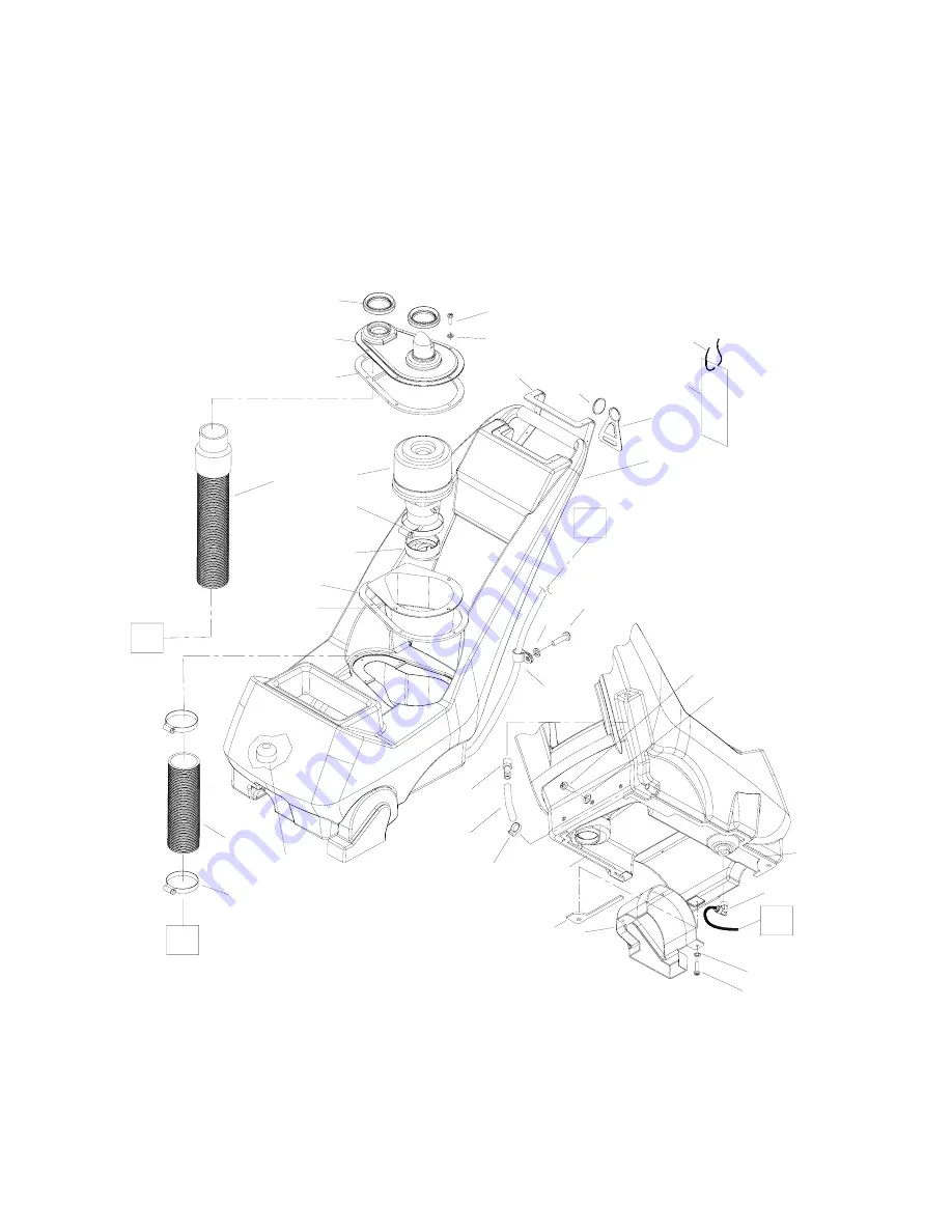
SOLUTION TANK ASSEMBLY
CDT7IHB 86036840 03/12/07
5-13
6
16
14
18
5
4
2
8
11
22
15
19
12
17
23
13B
7
3
29
10
1
9
21
20
A
B
D
C
25
24
27
26
28
30
33
32
13A
13
(SEE FRAME)
(SEE CONTROL PANEL)
(SEE PUMP)
Page 1: ...rating the machine Bitte lesen Sie diese Anleitungen bevor Sie die Maschine in Gebrauch nehmen MODEL CDT7IHB 10080240 Operating Instructions ENG Bedienungsanleitung GER 8 603 684 0 M 04 26 11 PRV NO 9...
Page 2: ...nk you for purchasing a Windsor product Warranty registration is quick and easy Your registration will allow us to serve you better over the lifetime of the product To register your product go to www...
Page 3: ...on Tank 3 5 Machine Operation 3 6 Cleaning Procedure 3 9 Accessory Tool Usage 3 10 MAINTENANCE Periodic Maintenance 4 1 Daily Regular Maintenance 4 1 Vacuum Motor Replacement 4 2 Belt Replacement 4 3...
Page 4: ...ins preventive maintenance to keep the machine and its components in good working condition They are listed in this general order Vacuum Motor Replacement Belt Replacement Solution Pump Replacement Th...
Page 5: ...thorized service center Do not pull or carry machine by electrical cord use as a handle close a door on cord or pull cord around sharp edges or corners Do not run machine over cord Keep cord away from...
Page 6: ...safe operation of equipment Report machine damage or faulty operation immediately Do not use the machine if it is not in proper operating condition Following is information that signals some potentia...
Page 7: ...036840 03 12 07 2 3 NOTE These drawings indicate the location of safety labels on the CDT7IHB If at any time the labels become illegible contact your Windsor representative for prompt replacement WARN...
Page 8: ...I diaphragm style internal bypass SOLUTION CAPACITY 7 gallons 26 5ltr RECOVERY CAPACITY 7 gallons 26 5ltr BRUSH SPEED 1000 rpm GENERAL DIMENSIONS WEIGHT Vacuum shoe 17 43 18 cm cast aluminum with spri...
Page 9: ...lve to dispense solution to floor through jets Intermittent off and continuous settings 5 Vacuum Motor Switch Turns on vacuum motor 6 Brush Motor Circuit Breaker 4 amp Breaker protecting brush motor 7...
Page 10: ...ct various auxiliary 1 1 2 inch cleaning tool vacuum hoses 3 Brush Height Adjustment Used to regulate brush height from storage position to various carpet heights 4 Recovery Tank Used to collect dirty...
Page 11: ...CONTROLS COMPONENT LOCATIONS CDT7IHB 86036840 03 12 07 3 4 1 Solution Intake Cover 2 Vacuum Intake Cover 3 Float Shut Off 4 Clean Out Opening 5 Pour Spout 6 Lift Handle 2 1 3 4 5 6 6...
Page 12: ...tank CHEMICALS Suitable Chemicals Non Compatible Chemicals Alkalis Aldehydes Detergents Aromatic Hydrocarbons Hydroxides SP Butyls Soaps Carbon Tetrachloride Vinegar Clorox Chlorinated Bleaches Chlori...
Page 13: ...or good operation the brush must skim the carpet If circuit breaker trips raise brush to prevent damage to motor or carpet Plug cord into grounded outlet Note Be sure dome is seated on recovery tank a...
Page 14: ...the on position with the thumb and is typically used in small areas where short cleaning passes are made The continuous setting allows the operator to set the switch in the on position with one touch...
Page 15: ...drive belt side of machine During operation observe the following The Cadet is equipped with clear internal covers to facilitate operator viewing of dirty solution and vacuum air flow During operatio...
Page 16: ...hose Use a hose with cold water to clean out the recovery tank Also drain solution tank after each use STEP 7 STEP 8 After cleaning turn off all controls return brush to storage position and carefully...
Page 17: ...s in storage position Squeeze handle on accessory tool to begin cleaning STEP 3 STEP 4 STEP 1 STEP 2 Use only one of the following acceptable accessory tools 86000000 PRV NO DDH 86041180 PRV NO ESW 86...
Page 18: ...urce 1 Empty unused cleaning solution from the solution tank 2 Inspect and clean filter screen in solution tank 3 Flush pumping system with 4 or 7 liters of clean hot water 4 After each use rinse tank...
Page 19: ...ing will damage motor if brushes are allowed to wear away completely If armature commutator is not concentric extremely pitted or grooved the motor will need to be replaced or sent to a qualified serv...
Page 20: ...rews that hold the brush motor in place and slide motor forward to release tension in belt 5 Remove the 2 screws that fasten the vacuum shoe links p n 86227350 PRV NO 05016 to the brush housing 6 Remo...
Page 21: ...f the frame 4 Remove solution hoses from fittings in pump 5 Remove the 2 screws that fasten the pump to the frame 6 Reverse process to install pump Pump Head 86251040 PRV NO 65187 Pressure Switch 8616...
Page 22: ...oe 2 Dome gasket defective or missing 3 Vacuum hose cracked or hose cuff loose 4 Recovery tank full float ball stuck in the up position 1 Remove debris from vac shoe 2 Replace as necessary 3 Replace o...
Page 23: ...WIRING DIAGRAM CDT7IHB 86036840 03 12 07 4 6 86268750 PRV NO 88567 86268350 PRV NO 88270 86268900 PRV NO 88655 86001240 PRV NO 14020 86268750 PRV NO 88567 86003650 PRV NO 34362 86004480 PRV NO 41353...
Page 24: ...FRAME ASSEMBLY CDT7IHB 86036840 03 12 07 5 1 2 16 27 29 20 8 22 11 5 10 28 15 7 32 13 14 24 25 4 SEE PG 5 11 3 26 34 21 18 19 A 12 33 9 6 B 30 31...
Page 25: ...6580 70085 2 SCR 1 4 20 X 1 2 PPHMS SS 16 86273980 70066 2 SCR 10 32 X 3 4 PPHMS 17 OPEN 18 86010630 87013 2 WASHER 1 4 ID X 5 8 OD SS 19 86010660 87025 2 WASHER 1 4 LOCK EXT STAR SS 20 86010650 87018...
Page 26: ...BRUSH ASSEMBLY CDT7IHB 86036840 03 12 07 5 3 31 25 29 30 18 38 39 16 30 34 17 20 37 26 24 11 8 15 3 26 19 6 21 35 28 29 25 17 32 23 14 30 22 4 27 1 16 7 10 12 13 25 40 41 42 43 33 45 36 44 47...
Page 27: ...192 1 PIN ROLL 1 4 X 1 25L 23 86006430 67411 1 ROLLER 1 9 DIA X 10 5 LG 24 86006510 70043 2 SCR 10 32 X 5 8 PFHMS 25 86006590 70088 8 SCR 10 32 X 1 2 PPHMS SS DL 26 86006650 70177 7 SCR 10 32 X 1 2 FH...
Page 28: ...PUMP ASSEMBLY CDT7IHB 86036840 03 12 07 5 5 29 8 14 27 SEE SOLUTION 20 C 26 24 26 12 23 2 9 17 21 16 7 20 1 18 19 15 11 5 6 16 10 13 3 TANK 28 29 28 4...
Page 29: ...03640 34355 1 FITTING 1 4 TUBE Y QC 13 86008360 78419 1 TEE 3 8 MPT X 3 8 TUBE QC 14 86010570 84165 1 VALVE ASM SOLENOID CLP FAMILY 15 86010810 87191 2 WASHER 1 4 IDX1 0OD FLAT SS 16 86010650 87018 4...
Page 30: ...PUMP ASSEMBLY CDT7IHB 86036840 03 12 07 5 7 3 4 13 10 16 6 5 11 15 19 18 1 20 7 16 21 17 9 2 12 25 26 23 28 24 26 C 20 SEE SOLUTION 27 14 8 TANK PRIOR TO SERIAL 1000153482...
Page 31: ...6003640 34355 1 FITTING 1 4 TUBE Y QC 13 86008370 78420 1 TEE 1 4 MPT X 3 8 TUBE QC 14 86010570 84165 1 VALVE ASM SOLENOID CLP FAMILY 15 86010810 87191 2 WASHER 1 4 IDX1 0OD FLAT SS 16 86010650 87018...
Page 32: ...VACUUM SHOE ASSEMBLY CDT7IHB 86036840 03 12 07 5 9 4 7 13 11 3 10 7 5 6 11 8 2 1 12...
Page 33: ...SCR 10 32 X 3 8 HHTR W STAR 5 86275120 70360 4 SCR 1 4 20 X 75 PPHMS PHIL 6 86006840 70390 4 SCR 1 4 20 X 1 FHCS PLTD 7 86008130 73958 8 SPACER 3 8ODX 058WX 2814 CRS 8 86010620 85039 1 VAC SHOE 15 9 O...
Page 34: ...CONTROL PANEL ASSEMBLY CDT7IHB 86036840 03 12 07 5 11 20 12 16 11 4 9 14 5 13 15 19 6 1 18 17 10 7 2 8 3 D SEE SOLUTION TANK 21...
Page 35: ...PANEL CADET CONTROL 9 86006950 70532 9 SCR 10 32 X 1 2 PPHMS BLK NP 10 86006710 70235 2 SCR 6 32 X 1 0 PH BLK NYLON 11 86007120 72126 1 SWITCH DPDT 3 POSITION ROCKER 12 86007140 72130 2 SWITCH SPST 2...
Page 36: ...ON TANK ASSEMBLY CDT7IHB 86036840 03 12 07 5 13 6 16 14 18 5 4 2 8 11 22 18 15 19 12 17 23 13B 7 3 29 18 10 1 9 21 20 A B D C 7 25 24 27 26 28 30 33 32 13A 13 SEE FRAME SEE FRAME SEE CONTROL PANEL SEE...
Page 37: ...86135330 140688 BRUSH SET 230V VAC MTR WINDSOR SERVICE ONLY 14 86006600 70114 2 SCR 10 X 3 4 PPHST TYPE B 15 86006590 70088 2 SCR 10 32 X 1 2 PPHMS SS 16 86032240 75257 1 TANK CDT SOLUTION 17 86259060...
Page 38: ...RECOVERY TANK ASSEMBLY CDT7IHB 86036840 03 12 07 5 15 E E 18 5 7 15 11 12 14 12 9 1 10 2 6 13 8 4...
Page 39: ...630 34351 1 FLOAT SHUT OFF 7 86003910 35230 1 GASKET DOME 8 86003930 35232 2 GASKET PORT COVER 9 86004200 39353 1 HOSE 1 5 X 12 0 DRAIN 10 86004510 41391 1 HOSE INSERT 11 86004500 41390 1 HOSE CAP 12...
Page 40: ...SM SOLENOID CLP FAMILY 86010570 84165 GASKET ACCESSORY PORT 86003780 35171 BREAKER 7A CIRCUIT 86230110 14312 BREAKER 4A EURO CIRCUIT 86002020 14949 SWITCH SPST 2 POSITION ROCKER 86007140 72130 SWITCH...
Page 41: ...CDT7IHB 86036840 03 12 07 5 18...