12
BEETLE /iPOS plus User Manual
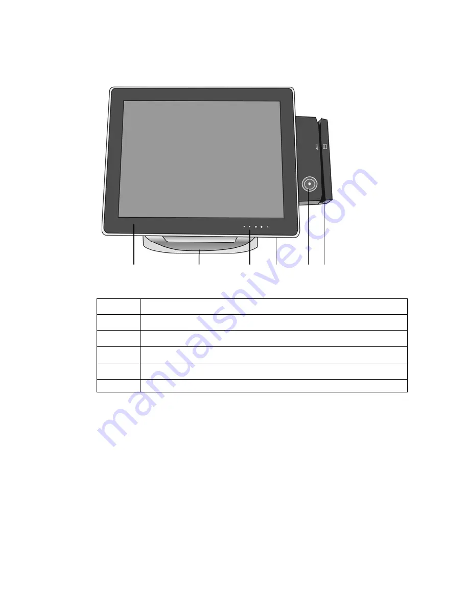
Front Side View: Device with Monitor Stand
Display
Pedestal
Brightness adjustment, LEDs
Power button
Waiter lock (optional)
⑥
Swipecard reader (optional)
Page 1: ...BEETLE iPOS plus All in one POS System User Manual ...
Page 2: ...f you have any constructive criticism We would like to thank you in advance for your comments With kind regards Wincor Nixdorf International GmbH Technical Documentation R D SAT36 Wohlrabedamm 31 D 13629 Berlin E Mail retail documentation wincor nixdorf com Order No 01750245230A Your opinion ...
Page 3: ...BEETLE iPOS plus All in one POS System User Manual Edition August 2013 ...
Page 4: ... GmbH 2013 The reproduction transmission or use of this document or its contents is not permitted without express authority Offenders will be liable for damages All rights including rights created by patent grant or registration of a utility model or design are reserved Delivery subject to availability technical modifications possible ...
Page 5: ...ng the System 7 Basic Settings 8 Components 8 Processor Type 8 RAM 8 Hard Disk Options 8 Display 8 Setting Up the Device 9 Ergonomic Terminal Workplace 9 Overview 11 Front Side View Wall Fastening 11 Front Side View Device with Monitor Stand 12 Back Side View 13 AC Power Adapter 14 Projected Capacitive Touch Screen 15 General Information 15 Instructions for Using the Touch Screen 15 Brightness 16 ...
Page 6: ...ructions 32 Magnetic Swipe Card Reader Installation 32 Fingerprint Reader option 35 Waiter Lock option 36 Customer Display option 37 Cleaning Instructions 38 Customer Display Installation 38 Starting Up the System 41 Appendix 43 Technical Data 43 Interfaces J2 44 AC Power Adapter 44 Power Cable Selection 45 Capacity of External I O Ports 45 Total Current Consumption Of Interfaces 46 Wall Mounting ...
Page 7: ...on Serial Port 3 57 Sub Menu Super I O Configuration Serial Port 4 57 Sub Menu Super I O Configuration Serial Port 5 58 Sub Menu Super I O Configuration Serial Port 6 58 Sub Menu H W Monitor 58 Sub Menu PPM Configuration 59 Sub Menu BIOS Info Menu 59 Chipset Menu 60 Sub Menu Host Bridge 60 Sub Menu Host Bridge Intel IGD Configuration 60 Sub Menu South Bridge 61 Boot Menu 62 Option ROM Messages 3 6...
Page 8: ...Test Points Codes 66 Checkpoint Ranges 66 SEC Phase 66 PEI Phase 67 PEI Beep Codes 69 DXE Phase 70 DXE Beep Codes 72 Abbreviations 73 ...
Page 9: ...n radiate radio frequency energy and if not installed and used in accordance with the instruction manual may cause harmful interference to radio communications Operation of this equipment in a residential area is likely to cause harmful interference in which case the user will be required to correct the interference at his own expense Modifications not authorized by the manufacturer may void users...
Page 10: ... such as a heat radiator before beginning to work with ESD labeled components Likewise all equipment and tools used in working with such compo nents must be free of static charge Pull the mains plug before inserting or removing such components Only handle such components by their edges Never touch any terminal pins of the strip conductors on such compo nents Safety Notes The BEETLE iPOS plus confo...
Page 11: ...d and the Customer Service of Wincor Nixdorf or your dealer must be notified Your BEETLE system is the result of modern technical innovation So please see for according structural and technical surroundings to guar antee a faultless and efficient work of your BEETLE Therefore you should connect your BEETLE or other IT devices only to power supply systems with separately guided protective earth con...
Page 12: ...ncor Nixdorf Inter national GmbH branch office or your dealer About This Manual This documentation is intended to help you to work with the POS system and to serve as a reference work The detailed table of contents help you find the desired information quickly and easily Notes in the manual are marked by this symbol This symbol is used for warnings The type and scope of application programs depend...
Page 13: ...system is manufactured without the use of CFC and CHC and is produced mainly from reusable components and materials Please do not stick labels onto plastic case parts This would help us to re use components and material But there are still some parts that are not reusable Wincor Nixdorf Inter national GmbH guarantees the environmentally safe disposal of these parts in a Recycling Center which is c...
Page 14: ...insufficient maintenance improper use of the product or unauthorized modifications of the product inadequate location or surroundings will not be covered by the warranty For further information on the stipulation consult your contract All parts of the product which are subject to wear and tear are not included in the warranty engagement For detailed warranty arrangements please consult your contra...
Page 15: ...sition may be installed Should you notice any transport damages or discrepancies between pack age contents and delivery ticket or functional defects please inform your contracting parties or the branch office of Wincor Nixdorf immediately Please indicate the number of your delivery ticket and delivery ticket position and serial numbers of the respective devices The serial number can be found on th...
Page 16: ...dditional peripheral devices are delivered separately for example the swipe card reader The modules must still be mounted to the system Components The BEETLE iPOS plus configuration can consist of the following components Processor Type Atom Dual Core Processor RAM 2GB or 4GB Hard Disk Options HDD SATA 2 5 160GB or SSD 2 5 32GB 64GB respective 128GB Display 15 1 projected capacitive touch screen ...
Page 17: ... the BEETLE iPOS plus system where it will not be exposed to extreme environmental conditions Protect the device from vibrations dust moisture heat and strong magnetic fields Ergonomic Terminal Workplace Please observe the following when setting up your terminal workplace Avoid direct glaring and reflective glaring Use the screen only in a controlled luminance surounding Install the device with a ...
Page 18: ...ETLE iPOS plus User Manual Position the screen within a preferred and permit ted range of vision so that you can look onto the screen from above 30 30 40 0 Permitted range of vision Preferred range of vision ...
Page 19: ...BEETLE iPOS plus User Manual 11 Overview Front Side View Wall Fastening Display Brightness adjustment LEDs Power button Waiter lock optional Swipecard reader optional ...
Page 20: ...12 BEETLE iPOS plus User Manual Front Side View Device with Monitor Stand Display Pedestal Brightness adjustment LEDs Power button Waiter lock optional Swipecard reader optional ...
Page 21: ...BEETLE iPOS plus User Manual 13 Back Side View Module waiter lock swipecard reader optional Pedestal Customer display optional ...
Page 22: ...apter Power Connector DC Power Out Current Supply to BEETLE iPOS plus The external power supply is applicable for common line voltage It automatically adjusts itself to the particular voltage for grid input voltage and power supply see appendix ...
Page 23: ...itive touch screens which were used until now is located on the back side of the touch screen Thus the active touch surface is not touched directly anymore and therefore will not wear off by normal use As most of the surface contaminations do not cause an interference of the touch screen this technology can be used in public or under severe environmental conditions Instructions for Using the Touch...
Page 24: ...ttom of the display increasing brightness decreasing brightness LEDs The LEDs are at the bottom of the display with the following meaning LAN hard disk power LAN LED lights white Network connected HDD SSD LED flashes white read and write access to HDD SSD Power LED lights white The device is switched on ...
Page 25: ...ning product All pH neutral materials pH 6 to 8 are good for cleaning Cleaners with pH values 9 to 10 are not recommended Cleaning with water and isopropyl alcohol is possible as well Do not use solvents con taining acetic acid Use a soft fine meshed cloth to clean the surface Dampen the cloth slightly and then clean the screen A wrong maintenance may cause damages to the screen which are not cove...
Page 26: ...s All devices belonging to the modular BEETLE iPOS plus that have a separate power cable must be connected to the same electric circuit Connect the system as described below Tilt the system to the back Pull the cable cover forwardly out of the guide see arrows ...
Page 27: ...estal by lifting it upwards and slightly forwards Guide the power cable from the power supply unit through the pedestal to the front 1 and open the cable duct 2 Connect the power cable with the dedicated socket 3 Lay the cable through the cable duct Proceed the same way with all the other cable connections LAN Mouse etc Then close the cable duct 4 ...
Page 28: ...anual Reinsert the pedestal s cover Make sure that the strip corresponds to the notch at the pedestal see arrow The cover of the pedestal must engage and sit flushwith the pedestal Push the cable cover backwards until it engages ...
Page 29: ...r side of the external power supply unit Now connect the power supply unit to the in house grounded socket Then you can switch on the system see white arrow Shortly press the Power button at the front side to start the system Never connect data cables when the system is switched on ...
Page 30: ...onnecting peripherals with the system switched on is not allowed Example for a connector panel Audio Line Out Connection to power supply ext power supply RJ12 socket cash drawer RJ45 socket LAN 2 x USB A USB 2 0 1 x USB powered 12V 2A max 15 pin D Sub socket 2 x D Sub COM interfaces with power supply Mass storage HDD SSD Make sure that all additional devices have an CE certificate ...
Page 31: ...in when you insert them Power is supplied to the cash drawer via this socket P24V 5 15 Connecting daisy chained cash drawers and 12V OEM drawers is prohibited Connect cash drawers only no telephone RJ45 LAN The system can be connected to a network LAN from the back panel LEDs left LED lights green Network connected flashes green Data transfer right LED off 10 MBit lights green 100 MBit lights oran...
Page 32: ...or customer displays The power supply is 12V This interface can also be used as a USB A socket CRT You can connect a monitor to the BEETLE iPOS plus via the 15 pin D sub jack An LCD screen can be connected alternatively if a TFT adapter is installed D Sub Jack Power Supplied COM1 COM2 The interface connection is a 9 pin D sub jack for scanner user or customer displays without own power supply Make...
Page 33: ...from the grounded contact power sockets Unplug all data communication cables from the sockets of the data networks Unplug all cables from the devices With MINI DIN plugs Wincor Nixdorf keyboards the plug remains inserted until released Pull the plastic covering from the connecting socket with your thumb The lock is released The metal of the plug is visible To release a RJ12 plug push the latch und...
Page 34: ...User Manual The P USB connector is disengaged by pressing the spring that is marked by an arrow Manually loosen the knurled screws of the COM or DVI interface connector To release a RJ45 plug push down the latch see arrow ...
Page 35: ...rive is a data storage drive that uses memory elements in place of a rotating disk to store data The SSD easily substitutes the hard disk and emulates a hard disk drive interface The most SSDs are flash memory based Change Of the Hard Disk Drive First ensure that the device is switched off and that the power connector is disconnected Tilt the system to the back ...
Page 36: ...User Manual Pull the cable cover forward out of the guide see arrows You find the HDD or SSD in the drive carrier see arrow Remove both screws M3 x 7 that fix the drive carrier to the housing and pull out the drive carrier ...
Page 37: ...ows Take the HDD SSD out of the carrier Handle the hard disk with care while removing or mounting it Do not touch exposed electronics Install the new hard disk SSD and fix it with the screws removed before Mind the correct fitting position see illustration Data transfer Electrical connection ...
Page 38: ...with new HDD or SSD into the system again Fix the carrier to the housing with the two screws Push the cable cover into the guide until it engages Now connect the device to the mains voltage and switch it on by pressing the power button at the front side ...
Page 39: ...ugh the slit of the swipe card reader from top to bottom in a quick and steady movement Make sure that the magnetic strip is to the right When using swipe cards observe the following Swipe cards should only be inserted in the top of the specially designed slit of the reading device If the card is inserted in another place this could damage the reading head Swipe cards should never be allowed to co...
Page 40: ...a special cleaning card that can be purchased from Wincor Nixdorf Magnetic Swipe Card Reader Installation Always make sure that the display is switched off when you do cabling works Connecting peripherals with the system switched on is not allowed Unpack the parts and check whether the delivery matches the details of the delivery note The delivery contains the Magnetic Swipe Card Reader MSR and tw...
Page 41: ... Manual 33 You will find a flap at the rear side of your system at the position for the SwipeCard Reader Remove this flap using a small screw driver Connect the cable connectors and lay the cables into the openings provided ...
Page 42: ...BEETLE iPOS plus User Manual Place the Swipe Card Reader and tighten it with the supplied screws Now connect the device to the mains voltage and switch it on by pressing the power button at the front side ...
Page 43: ...his identification method is very efficient and reliable Even with low light intensity the device will provide an excellent image quality Handling is very comfortable Just put your finger on the blue glowing window The reader quickly and automatically will scan your fingerprint For more information about function and handling contact Digital Persona www digitalpersona com ...
Page 44: ...16 digit key number also safe for clear identification The operation of the system is very simple the key is placed onto the magnetic probe see figure The key is held magnetically to the probe and transmits the data by an electrical USB interface The readout of the data may be integrated easily in a software application Programming the Electronic Key Controller for the Waiter s Lock is described i...
Page 45: ... characters The standard character set and corresponding country code are implemented Implementation of VFD technology ensures that the customer display is ergonomically designed to achieve a high degree of readability irrespective of the cashier s angle of vision The voltage 12 V DC is also supplied via this interface The display module is installed at the rear side of the system Display Module ...
Page 46: ...Do not use solvents con taining acetic acid Use a soft fine meshed cloth to clean the surface Dampen the cloth slightly and then clean the screen A wrong maintenance may cause damages to the screen which are not covered by guarantee or warranty Customer Display Installation Always make sure that the display is switched off when you do cabling works Connecting peripherals with the system switched o...
Page 47: ...User Manual 39 You will find a flap at the rear side of your system at the mounting position for the Customer Display Remove this flap using a small screw driver Connect the cable connectors and carefully lay the cables ...
Page 48: ...nsert the display into the opening until it engages Flap the display upwards and tighten it with the delivered screws Now connect the BEETLE iPOS plus to the mains voltage and switch it on by pressing the power button at the front side ...
Page 49: ...to be booted Each medium is assigned a logical drive according to the configuration of your BEETLE iPOS plus The following media can be assigned a drive Network Hard disk drive solid state drive USB drive The logical drives are designated C and D The network is always assigned to the C drive during the runup procedure The hard disk can be assigned to the C or D drive The system can only be started...
Page 50: ... system started up without an error the application software is automatically booted if necessary A message is displayed as soon as the BEETLE iPOS plus is ready for operation For more detailed information see the manual for your application program ...
Page 51: ...194 mm Height 315 mm Weight ca 5 9 kg Climatic Category Class 3K3 DIN IEC 721 3 3 Class 2K2 DIN IEC 721 3 2 Class 1K2 DIN IEC 721 3 1 Temperature Operating 3K3 0 C up to 40 C Transport 2K2 25 C up to 60 C Storage 1K2 RT 15 C up to 60 C PCT 20 C up to 60 C Input Voltage 24 V Max Power Consumption 7 5 A ...
Page 52: ...bit s AC Power Adapter Only use power supply units PSU released or approved by Wincor Nixdorf The PSU has to comply with the following minimal requirements and common standards Rated input voltage 110VAC 240VAC Rated input current 2 5 1 25A Input frequency range 47 63 Hz Rated output voltage 24V 5 Rated output current 7 5A Max output power 180W at ambient 25 degree C 135W at ambient 40 degree C 85...
Page 53: ...rts The capacity of the I O ports is determined by the used power supply unit The table next page shows a list of free external I O ports and the corresponding power ratings Before connecting additional peripherals to these ports the user must check and ensure that the power consumptions of the peripherals do not exceed the maximum output power of the ports and that the total power consumption doe...
Page 54: ...es The total current consumption at 5V interfaces must not exceed 5A Each COM 300mA in total 500mA Each USB 500mA in total 2A Max 5A 5V The total current consumption at 12V interfaces must not exceed 5A Each COM 600 mA in total 900mA Each USB 1 5A in total 2A Max 5A 12V ...
Page 55: ... that all cables are unplugged and the system is disconnected from the main power supply Lay the BEETLE iPOS plus screen side down on a scratch free soft work surface and remove the cable cover out of the guidance Flap the pedestal downwards and loosen the two screws M4 x 6 that hold the swivel joint cover see arrows below Swivel joint cover ...
Page 56: ... the pedestal Loosen these four screws and remove the pedestal Now you can install the BEETLE iPOS plus to a VESA standard wall mount Plug the cable connections and switch the system on by pressing the pow er button at the front side You need to contact us or suitable agency for correct wall mounting ...
Page 57: ...stem holds the Setup utility When you turn on the system it will provide you with the opportunity to run this program This appears during the Power On Self Test POST Press F2 to call the Setup utility If you missed the opportunity to press the mentioned key POST will continue with its test routines thus preventing you from calling Setup If you still need to call Setup reset the system by pressing ...
Page 58: ...dio power loss behavior and wake up on USB Boot Use this menu to configure the default system device used to locate and load the Operating System Security Use this menu to enable a supervisor or user password and Intrusion Detection Save Exit Use this menu to exit the current menu or specify how to exit the Setup program To access the menu bar items press the right or left arrow key on the keyboar...
Page 59: ...d down keys to scroll through the entire help document Press Home to display the first page press End to reach the last page To exit the help window press the Enter or Esc key Sub Menu Note that a right pointer symbol appears left of certain fields This pointer indicates that a sub menu can be launched from this field A sub menu contains additional options for a field parame ter To call a sub menu...
Page 60: ... specify usually the current date The format is month day year Valid values for month day and year are Month 1 to 12 Day 1 to 31 Year up to 2079 System Time XX XX XX Sets your system to the time that you specify usually the current time The format is hour minute second Valid values for hour minute and second are Hour 00 to 23 Minute 00 to 59 Second 00 to 59 Press Enter to terminate every entry val...
Page 61: ...nd Disabled Wake Up By Ring Disabled This allows enabling or disabling power up the BEETLE when the modem receives a call while the BEETLE is in Soft Off or Hibernate mode The BEETLE cannot receive or transmit data until the system and applications are fully running thus connection cannot be made on the first try Turning an external modem off and then back on while the BEETLE is off causes an init...
Page 62: ...akeup events are available from different power states Standby S3 Front Button Yes LAN Note1 Yes Modem Note1 Yes Time Note2 Yes USB Yes Note 1 Yes is valid only if the option Wake Up By Ring is Enabled Note 2 Yes is valid only if the option Wake system with Fixed Time is Enabled Sub Menu CPU Configuration CPU Configuration Processor Type Intel ATOM CPU EMT64 Supported Processor Speed 2xxx MHz Syst...
Page 63: ...ed Configure SATA as IDE The onboard printed SATA port numbers have the following references to the setup entries SATA1 SATA Port 0 SATA2 SATA Port 1 SATA Controller s Enabled This option handle the onboard SATA Controller The options are Enabled or Disabled Configure SATA as IDE Select a configuration mode for SATA Controller The options are AHCI IDE or Hard Disk Pre Delay Sub Menu USB Configurat...
Page 64: ...his setup point and after detecting of this USB device from the UEFI BIOS you have to switch the boot order to the appropriate device In the AUTO mode is the USB support switched off when no Legacy USB device was found Configuration Options Disabled Enabled Auto Device power up delay Auto Some USB device uses longer time to initialize Maximum time the device will take before it properly reports it...
Page 65: ...ration Serial Port 2 Configuration Serial Port 2 Enabled Device Settings IO 2F8H IRQ 3 Change Settings IO 2F8H IRQ 3 Sub Menu Super I O Configuration Serial Port 3 Configuration Serial Port 3 Configuration Serial Port 3 Enabled Device Settings IO 3E8h IRQ 5 Change Settings IO 3E8h IRQ 5 Sub Menu Super I O Configuration Serial Port 4 Configuration Serial Port 4 Configuration Serial Port 4 Enabled D...
Page 66: ...guration Serial Port 6 Configuration Serial Port 6 Enabled Device Settings IO 2F0h IRQ 10 Change Settings IO 2F0h IRQ 10 This setup screen shows the programmed values of the onboard legacy serial ports Configuration options Enabled Disabled Sub Menu H W Monitor Pc Health Status CPU temperature 34 C system temperature 27 C CPU Voltage 1 184 V DRAM Voltage 1 488 V 24 V 24 460 V 12 V 11 968 V 5 V 5 0...
Page 67: ...ate of CMOS Battery A discharged battery will reported during the POST Sub Menu PPM Configuration PPM Configuration CPU C state Report Enabled Enhanced C state Enabled CPU C6 state Enabled These settings allow the configuration of different sleep modes used by the processor Sub Menu BIOS Info Menu When the sub menu is accessed the following info screen appears PRODUCT NAME J2 0 NM10 AiO BIOS VERSI...
Page 68: ...Power Supply The default placeholders may be replaced by specific data from factory describing configuration serial number etc for each device Chipset Menu Host Bridge South Bridge Sub Menu Host Bridge Intel IGD Configuration Sub Menu Host Bridge Intel IGD Configuration Intel IGD Configuration IGFX Boot Type LCD LCD Panel Type 1024x768 24Bit 1ch Fixed Graphics Memory Size 128MB Fixed Graphics Memo...
Page 69: ...e rebooted after power has been interrupted Stay off leaves your system off and Last State reboots your system if it was active before power loss Is the key Follow AC Power selected the system will start up anytime power is available Configuration options Stay off Last State Follow AC Power In mode Follow AC Power the front button is disabled This means that there is no way to force down the syste...
Page 70: ... booting Please select boot device SATA PM San Disk SSD U100 32G Enter Setup Boot Configuration Setup Prompt Timeout 3 Bootup NumLock State On Display POST Logo Disabled Option ROM Messages Force BIOS Launch PXE OpROM Disabled Set Boot Priority 1st Boot Network 2nd Boot Hard Disk 3rd Boot CD DVD 4th Boot USB KEY 5th Boot USB Hard Disk 6th Boot USB Floppy 7th Boot USB CD DVD 8th Boot UEFI BBS Prior...
Page 71: ...r not If the option Keep current is chosen the current display mode stays confirmed Configuration options Force BIOS Keep current Launch Storage OpROM Disabled Handle the boot option ROM for legacy mass storage devices Configuration Options Disabled Enabled n Boot Device These menu entries are used to specify the boot sequence from the available devices Every entry from 1 till n specifies a boot d...
Page 72: ...ngth 3 Maximum length 20 Administrator Password User Password Administrator Password User Password This field allows you to set the password Highlight the field and press Enter Type a password and press Enter you can type from 3 to 20 alpha numeric characters Symbols and other characters are ignored To confirm the password type the password again and press Enter The password is now set to Enabled ...
Page 73: ...onfirmation is asked Select Ok to save changes and reset the system Discard Changes and Reset This option should only be used if you do not want to save the changes you have made to the Setup program If you have made changes to fields other than system date system time and password the system will ask for confirmation before exiting and reset the system Restore Defaults This option allows you to l...
Page 74: ...0x0F SEC errors 0x10 0x2F PEI execution up to and including memory detection 0x30 0x4F PEI execution after memory detection 0x50 0x5F PEI errors 0x60 0x8F DXE execution up to BDS 0x90 0xCF BDS execution 0xD0 0xDF DXE errors 0xE0 0xE8 S3 Resume PEI 0xE9 0xEF S3 Resume errors PEI 0xF0 0xF8 Recovery PEI 0xF9 0xFF Recovery errors PEI SEC Phase Status Code Description 0x00 Not used Progress Codes 0x01 ...
Page 75: ...memory CPU initialization CPU module specific 0x15 Pre memory North Bridge initialization is started 0x16 Pre Memory North Bridge initialization North Bridge module specific 0x17 Pre Memory North Bridge initialization North Bridge module specific 0x18 Pre Memory North Bridge initialization North Bridge module specific 0x19 Pre memory South Bridge initialization is started 0x1A Pre memory South Bri...
Page 76: ...ge initialization North Bridge module specific 0x3B Post Memory South Bridge initialization is started 0x3C Post Memory South Bridge initialization South Bridge module specific 0x3D Post Memory South Bridge initialization South Bridge module specific 0x3E Post Memory South Bridge initialization South Bridge module specific 0x3F 0x4E OEM post memory initialization codes 0x4F DXE IPL is started PEI ...
Page 77: ...iggered by firmware Auto recovery 0xF1 Recovery condition triggered by user Forced recovery 0xF2 Recovery process started 0xF3 Recovery firmware image is found 0xF4 Recovery firmware image is loaded 0xF5 0xF7 Reserved for future AMI progress codes Recovery Error Codes 0xF8 Recovery PPI is not available 0xF9 Recovery capsule is not found 0xFA Invalid recovery capsule 0xFB 0xFF Reserved for future A...
Page 78: ...c 0x6F North Bridge DXE initialization North Bridge module specific 0x70 South Bridge DXE initialization is started 0x71 South Bridge DXE SMM initialization is started 0x72 South Bridge devices initialization 0x73 South Bridge DXE Initialization South Bridge module specific 0x74 South Bridge DXE Initialization South Bridge module specific 0x75 South Bridge DXE Initialization South Bridge module sp...
Page 79: ...nt 0xAE Legacy Boot event 0xAF Exit Boot Services event 0xB0 Runtime Set Virtual Address MAP Begin 0xB1 Runtime Set Virtual Address MAP End 0xB2 Legacy Option ROM Initialization 0xB3 System Reset 0xB4 USB hot plug 0xB5 PCI bus hot plug 0xB6 Clean up of NVRAM 0xB7 Configuration Reset reset of NVRAM settings 0xB8 0xBF Reserved for future AMI codes 0xC0 0xCF OEM BDS initialization codes DXE Error Cod...
Page 80: ...ned error 0xDB Flash update is failed 0xDC Reset protocol is not available DXE Beep Codes of Beeps Description 1 Invalid password 4 Some of the Architectural Protocols are not available 5 No Console Output Devices are found 6 Flash update is failed 7 Reset protocol is not available 8 Platform PCI resource requirements cannot be met ...
Page 81: ...ub miniature ESD Electronically Sensitive Devices HDD Hard Disk Drive IEC International Electrotechnical Commission ISO International Organization for Standardization LAN Local Area Network LED Light Emitting Diode PEN Protective Earth Neutral Conductor RAM Random Access Memory SSD Solid State Disk flash medium TN S Terre Neutre Separé UL Underwriters Laboratory standards USB Universal Serial Bus ...
Page 82: ...Wincor Nixdorf International GmbH D 33094 Paderborn Order No 01750245230A ...